Why do we need a Beam Splitter?
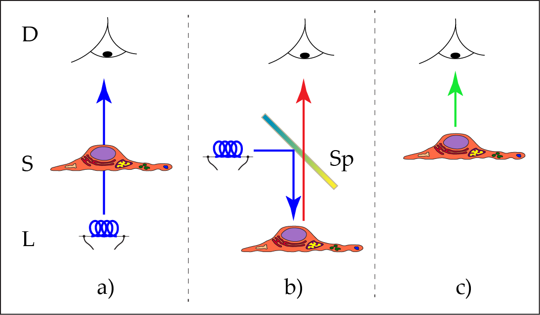
One possible segmentation of microscopic techniques refers to the direction, the light is applied to the microscopic subject (Figure 1). If the sample is in between the light source and the observer, i.e. the sample is ‘rayed’, then we use the term ‘transmitted light microscopy’. The alternative is having the illumination on the same side of the sample which is observed, known as ‘incident light microscopy’. As a matter of fact, our daily life observations are mainly concerned with incident light: the world around us is illuminated by sunlight or artificial light sources. We subsequently recognize the light that is reflected or scattered by objects, e.g. trees, cars, dangerous animals or humans. Transmitted light may occur in peculiar cases, for example if you examine a dead fly on your window pane.
When you look directly into a light source, like a candle, stars in the night sky, a firefly, or your TV screen (avoid the sun), then in this case we have a third type of observation: the perception of ‘self-luminous objects’. These objects do not need an illumination so, therefore, the terms ‘incident light’ and ‘transmitted light’ do not apply.
Incident light microscopy has become the most important technology in biomedical research, but also in other areas; especially in the form of fluorescence microscopy. The light is absorbed and, thereby, excites the fluorescent molecules – which usually have been incorporated into the specimen using artificial methods. After a time delay, the energy is released from the molecule, but with a longer wavelength (Stokes’ shift) than the incident light.
If we illuminate the sample with the desired color on the same side from which we also detect the emission signal, we must somehow separate the excitation and emission light. For this task, a beam-splitter is needed.
The classical way: a dichroic mirror
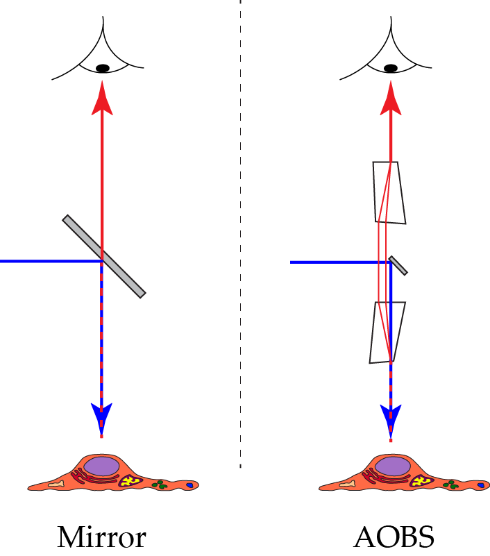
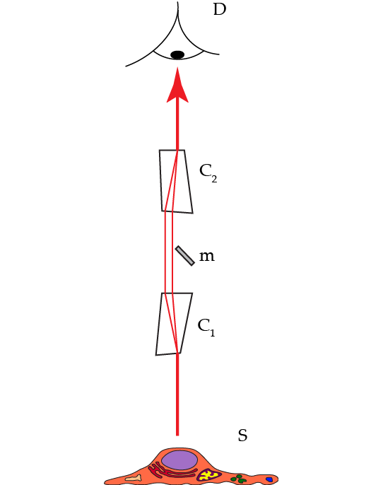
Incident illumination (also called: Epi-illumination) can be performed by shining light on the sample at an angle with respect to the microscope’s optical axis. This illumination mode was already described by Robert Hooke in 1665. An extreme variation of this method on the border between incident and transmitted illumination is light sheet microscopy (ultramicroscopy) with the illumination pointing perpendicular to the optical axis. Illumination coaxially to the optical axis has the advantage that the same high performance objective lens can be used both for illumination and detection. For this case, we must separate illumination and detection at some point behind the objective lens. The simplest way to do this, is to insert a semitransparent mirror into the beam path (Figure 2 “Mirror”).
For reflected light, a gray mirror would be the best solution. A gray mirror both reflects and transmits equal amounts of all colors, therefore it is also called a 50/50 beam splitter. In fluorescence, such a design would have the disadvantage that half of the precious fluorescence emission is lost. A workaround is the use of non-symmetrical gray splitters, e.g. 80/20 or even 95/5 splitters. Here, a larger part of the emission is rescued, but a greater part of the excitation light is wasted. This dilemma is solved by dichroic color splitters. They show alternating spectral bands of both high reflectivity and high transparency, depending on the design.
Dichroic mirrors are fabricated by depositing many thin layers of dielectric material onto a glass surface. Both the design and manufacturing are complex. Nevertheless, there are a large number of very different beam splitters available. These splitting mirrors may serve for a single type of fluorescence or for multiple excitations and emissions (Figure 3). For all cases, the mirror must reflect the excitation light within specific wavelength bands and transmit the emitted light in complementary bands. The emission efficiency is defined by the integral transparency of the emission band and the narrowness of the excitation band. In the case of multiband splitters, when excitation bands overlap with emission bands of the fluorescence signal, the efficiency is reduced.
The transmission efficiency of current dichroic beam splitters in the spectral regions of the emission is typically between 90% and 98% - sufficiently close to maximum transmission. Nevertheless, the widths of the reflection bands range is typically 25 nm (or less). Such a bandwidth is negligible for single-purpose splitters, if the excitation line is close to the edge where transmission begins. However, in most cases, multiple excitation bands are required, so a 25 nm bandwidth causes emission signal loss (depending on fluorophore emission).
The most significant parameter of a dichroic beam splitting mirror is the fact that the spectral parameters of a filter glass are not modifiable. If a change of excitation and emission properties is required, a different splitting mirror must be inserted into the beam path. Usually, a slider or a wheel is equipped with a number of different splitters, but rarely more than 5 pieces. This method has two consequences. First, the possible combination of excitation wavelengths is limited. Even if we assume a system equipped with 8 laser lines, then 255 different combinations would be possible. For maximum performance, a filter wheel or slider equipped with 255 different splitters is needed – not really a practicable solution. Therefore, in many cases a multiple band splitter must be used with a series of different fluorescent dye combinations and emission signal might be lost in the red part of the spectrum (see blue curve in Figure 3). The second handicap is the speed with which these filters can be exchanged. For a speedy change of illumination regimes, for example, cases where sequential recording of two sets of excitation is required or for excitation ratio-dyes, the filter set exchange rate is crucial. Standard gadgets offer switching times on the order of 1 second. Special designs may reach 0,1 seconds or little better.
Tunable beam splitting by means of acousto optical crystals
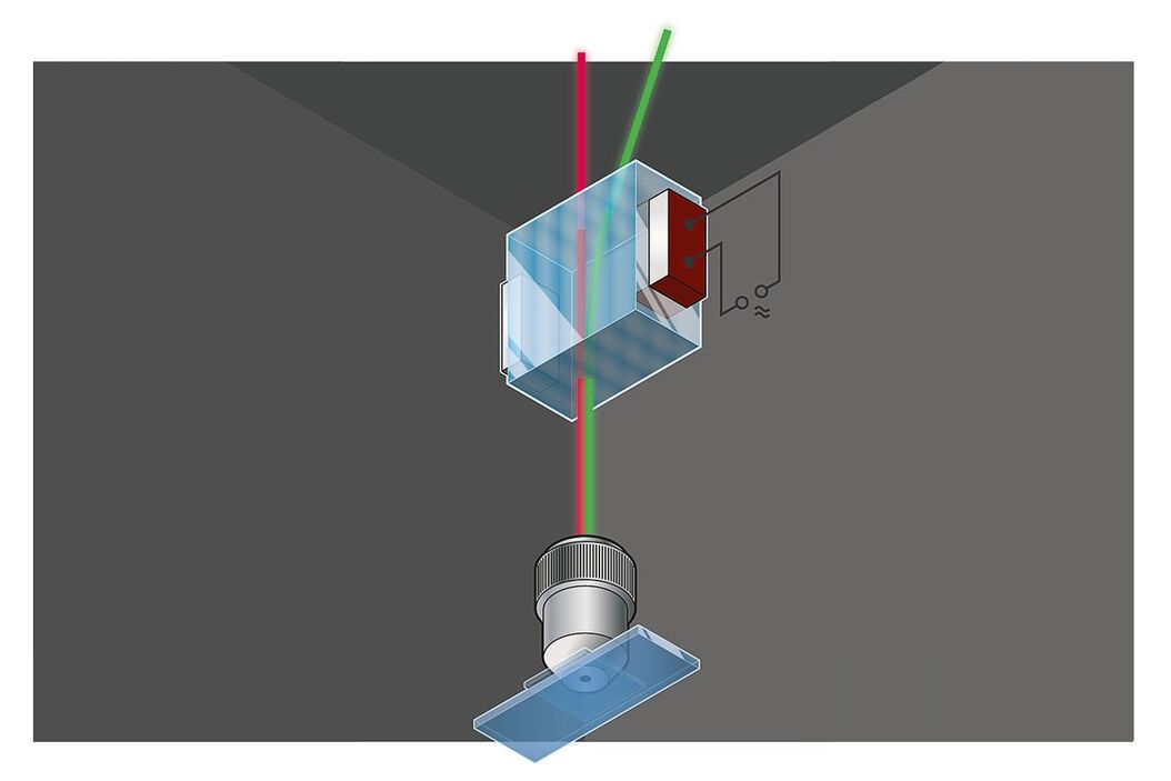
An entirely different way to separate the excitation and emission signals in incident light systems uses the properties of acousto-optically activated crystals (Figure 2 “AOBS”). The working principle of such devices is based on the fact that acoustic waves applied to an appropriate crystal causes select colors to exit the crystal at different angles as compared to the residual spectrum. Which colors are deflected and to which extent can be controlled by the frequency and the amplitude of the applied sonic wave. Moreover, it is possible to apply a whole series of acoustic waves and, thus, deflect a set of nearly freely selectable colors. The first application of such crystals in confocal microscopes led to the substitution of large arrays of selection filters in the excitation path.
A second implementation was the substitution of repositories of primary beam splitting mirrors. Here, the acousto-optical crystal is used in reverse mode. Acousto-optical devices are strongly polarization dependent, which poses no problem for laser excitation, as laser light is polarized anyway. To tackle the polarization split of the emission signal, appropriate measures have to be implemented. We will step briefly through the design of such a device below.
Laser light is coupled into the first crystal and exits from this crystal along the optical axis of the microscope to excite the sample (Figure 4):
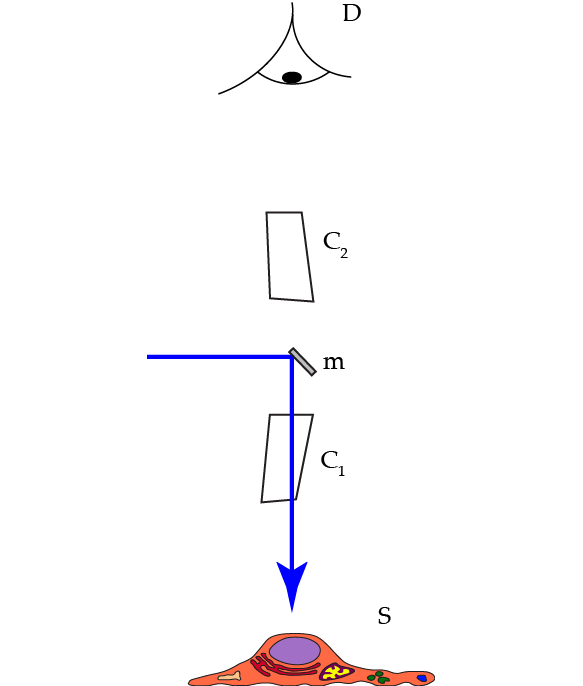
The light is coupled along the microscope’s optical axis via a small mirror. As laser light is polarized, the elements are arranged in such a way so that this polarization direction can excite the sample. Any other polarization directions would exit the crystal at a different angle. However, the laser light contains only one polarization direction. Lines may be switched by reprogramming within a few microseconds. As the programming frequency is freely tunable, so is the excitation color. If more than one excitation color is required, then all laser lines are fed coaxially in the same way into the beam path simultaneously (no multiplexing required). Again, regimes of excitations can be switched within microseconds.
The fluorescence emission is usually not polarized. The two directions are split in the first crystal and need to be combined (Figure 5).
The two polarization directions are combined in the second crystal and exit this crystal along the microscope’s optical axis. The light is then spatially filtered by the pinhole which generates the optical section - like in any other truly confocal microscope. Finally, the light is separated into spectral channels, detected, and images recorded.
The AOBS uses two acousto-optical crystals through which the emission light has to pass. Still, theaverage transmission is 95%, as shown in Figure 3 (red curve). The measurement shown in Figure 3 perfectly reveals an AOBS transmission of about 95% outside of the tunable excitation bandlets, i.e. in the transmission bands.
In fact, the different colors do not exit the second crystal at the same position. The rays are parallel, but not coaxial. Does this result affect the optical sectioning? Because the rays are parallel, they are focused onto exactly the same spot in the intermediate image where the pinhole is located. Optical sectioning performance with an AOBS system is identical to systems that employ different ways of separating excitation and emission light. Another question is: does the color dispersion influence the spectral performance? Yes, indeed, but we can make use of it: the spectral separation in the SP Detector from Leica Microsystems is realized via color dispersion by means of a prism. The spectrally “predispersed” beam is elegantly treated by the SP Detector and obtains only further beneficial properties.
Why the AOBS is superior to dichroic mirrors
The acousto optical beam splitter offers a whole series of beneficial features:
- There are never issues with improper adjustment of the various elements, as it is a single, mechanically fixed device.
- Electronic control of the generated waves leads to fast switching of lines within 10µs.
- The overall transmission of the device averages >95% for the fluorescence emission, because the crystals have a high performance anti-reflective coating.
- One device is good for any laser line, as the bandlet colors can be adjusted to any visible wavelength.
- Due to the freely tunable bandlet colors, the AOBS is the only device which makes the coupling of white light laser sources to confocal microscopes practical.
- It is possible to program a whole series of bandlets, allowing the AOBS to operate as a multiband splitter with currently up to 8 colors simultaneously. When combined with a white source, the number of possible combinations of excitations reaches the “gazillions”.
- Users can just select the desired excitation colors and the confocal system will arrange for appropriate filtering and splitting. There is no need for separate controls for the AOBS (primary beam splitting) and acousto-optical tunable filter (AOTF; line selection), because both are operated by identical devices.
References
- Birk H. et al: „Programmable beam-splitter for confocal laser scanning microscopy.” In: “Three-Dimensional and Multidimensional Microscopy: Image Acquisition and Processing IX” Eds Conchello JA, Cogswell CJ & Wilson T, Proceedings of SPIE Vol. 4621 (2002)
- Rietdorf J and Stelzer EKH: “Special optical elements” In: “Handbook of Biological Confocal Microscopy” Ed Pawley J. 3rd edition; Springer Heidelberg & New York. Chapter 3, pp 43-58 (2013)
- Birk H: „Optische Anordnung und Scanmikroskop“. Patentschrift DE 101 37 155 (2002)
- Borlinghaus RT: The White Confocal – Microscopic Optical Sectioning in all Colors. Springer International, Heidelberg (2017) ISBN 978-3-319-55561-4 (in press).
Related Articles
-
Coherent Raman Scattering Microscopy Publication List
CRS (Coherent Raman Scattering) microscopy is an umbrella term for label-free methods that image…
May 26, 2025Read article -

Unlocking the Secrets of Organoid Models in Biomedical Research
Get ready to delve deeper into the world of organoids and 3D models, which are essential tools for…
May 19, 2025Read article -

Super-Resolution Microscopy Image Gallery
Due to the diffraction limit of light, traditional confocal microscopy cannot resolve structures…
Mar 15, 2024Read article
