
Lens and mirror
, concave mirror (right).")
Optical instruments like microscopes, telescopes and binoculars use optical elements to produce an image of an object. The two most common elements for imaging objects are the converging lens and the concave mirror.
Lenses are more common in optical microscopes; therefore we will concentrate on lenses in the following exploration of the basic microscope functions. Concave mirrors are used for imaging purposes in reflective telescopes. Very often, concave mirrors are also used for illumination, like headlights in automotive applications.
Image formation through a lens
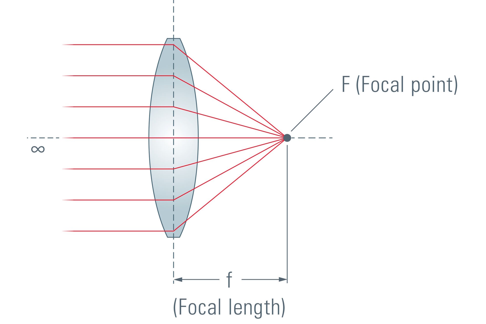
Before exploring how such a lens works, crucial terms and definitions of a lens have to be clarified. Everybody who ever (mis)used a magnifying glass as a burning glass has discovered that a lens creates a “hot spot” when pointed at the sun. This point is called the focal point. The distance from the center of the lens to this focal point is called focal length.
When reproducing this experiment with different types of converging lenses, one will discover that the focal length mainly depends on the curvature of the lens. In fact, a smaller radius of the curvature results in a shorter focal length. Another fact will be discovered: lenses with a large diameter are more “effective” than those with a smaller one. With this conclusion we have already defined two of the most important benchmark data of a lens: focal length and opening (diameter).
To simplify the handling of the lens diameter it is generally expressed in relation to the focal length. In the field of microscopy this parameter is called aperture (also: numerical aperture NA). Numerical aperture is defined NA = n sin α, where n is the refractive index of the medium filling the space between the object and the lens, and α is the half-angle of the maximum cone of light that can enter the lens (Figure 3). Photographers define the aperture of an objective by its f number. This is defined as the ratio of the focal length to the diameter of the lens (N = f/D) (Figure 4). In contrast to the NA value, small f numbers indicate a large aperture.


Again: What makes the image of an object sometimes smaller and sometimes larger than the object? The answer is: With a given focal length it is the relative distance that defines the size!
There is an important detail to take into consideration when talking about image generation: There are two “pivotal points” strictly linked to every lens: the focal points (one before and one behind the lens).
The following examples describe typical situations of images formed by a lens:
1. The object has an infinite distance to the lens
In this case parallel rays from the object to the lens are assumed. These are redirected in the lens to meet in the plane of the rear focal point and generate an image in the plane of the focal point.

2. The object is situated at a relatively large distance (e.g. 100 times the focal length)
This situation produces an image that is smaller than the object (approx. one 100th of the size of the original object).

3. The object is located at a distance twice the focal length in front of the lens.
This position creates an image of the object which is the same size as the object itself (reproduction scale 1:1). The image is found at a position twice the focal length from the rear side of the lens. By the way, this is the shortest overall distance you can have from object to image.

4. The object is situated in front of the focal point but within the range of twice the focal length.
Under these conditions, an image is generated which is larger than the object.

5. The object is located in the focal point of the lens.
In this case a virtual image, not a real one, is generated. The rays will leave the lens in a parallel manner. No image can be found unless we use another optical system e.g. our eye, which follows the conditions of case 1.

The above descriptions and diagrams have been simplified for easier understanding of basic optical principles. In reality, nearly all imaging elements consist of more than one lens. The above drawings present the optical element as an idealized “thin lens”. After exploring these standard situations of single-step imaging, we will now implement these findings into a two-step optical instrument: the compound microscope.
The compound microscope
The optical microscope magnifies an object in two steps. In both steps optical systems acting like converging lenses are used. The two components are used in two of the above mentioned situations:
- The first step is to place the object between the single and double focal point. The result is a magnified, real image. This microscope lens (in reality an optical system consisting of several lenses) is called the objective.
- Then a second lens is used to pick up this image exactly in its front focal point. As a result we generate a beam of parallel rays, but not a real image. This optical element is called eyepiece. The human eye is able to handle this parallel beam and generates an image onto its retina.
- Finally, this is what one can expect from a microscope: objects can be observed on a magnified scale with details undetectable by the naked eye.
A hint for practical use: the eye has to be placed a short distance above the microscope. Technically speaking, the pupil of our eye has to be located at the same place as the exit pupil of the microscope. This exit pupil can be easily seen when the light intensity of the microscope illumination is increased. It is the bright narrow spot visible above the eyepiece.
Correct positioning becomes particularly important when viewing with both eyes using a binocular tube. The distance between the two eyepieces has to be adjusted accurately to match the distance of the eyes.

How can we photograph microscopic images?
As the regular output of an optical microscope is a beam of parallel rays, a real image has to be produced first. Luckily, standard compact digital cameras include a lens (called objective) as our eye does. This lens can cope with objects at very far distances. Photographers call this distance "infinity". In other terms: rays from these objects reach us in a parallel manner.
When placing a compact camera behind the microscope’s eyepiece we are able to photograph through the microscope. To avoid frustration: the results obtained with this combination are very limited. This is because the optical design of compact cameras does not have microscopes in mind. Several dimensions (diameters, distances) limit practical use. Therefore dedicated digital cameras designed for the special conditions of optical microscopes are available for different applications.