
What is a pinhole?
Lens-based optical instruments are mainly concerned with two parameters: the lens curvature and the diameter. The curvature defines in which directions parallel rays are deflected, the diameter defines how much of those rays contribute to the resulting image. The diameter could simply be the frame of the lens, in many cases it is a separate diaphragm delimiting the beam diameter. Common diaphragms are made of lamellae by which the diameter of the diaphragm is controlled. Very tiny diaphragms, though, do not fit to current lamella-technology. The simplest way to generate a very tiny diaphragm is, to prick a cardboard or an aluminum foil with a needle (pin), therefore called a pin-hole. Such pinholes are the working principle of a “camera obscura”[1]
What is the purpose of the pinhole in a confocal microscope?
Confocal microscopes allow to optically separate slices of the sample’s response and record theses slices as images. Optimally, the slices cover just the depth of focus generated in the microscope.
To achieve this task, the sample is scanned by a tiny light point. The smallest shape that can be generated is a diffraction limited spot. A diffraction limited spot in the focal plane of the microscope is the image of a spot-shaped light source and therefore called “point spread function, psf”. The psf is the distribution of light in the focus of an optical device when imaging a dimensionless spot. As all conventional light sources are usually not spot-shaped but have a significant extension, the light source is projected on a tiny aperture, the pinhole, acting as a spot-shaped source.
On the detection side, the sensor must follow in an equal manner. That is, the sensing region should as well be a diffraction limited spot, at all times coinciding with the illumination spot. This is achieved by a similar arrangement: the emission light is fed through a tiny aperture, the detection pinhole, before recorded by a sensing element. It is this detection pinhole, which usually is referred to when we mention the “pinhole” in a confocal microscope.
The term “confocal” refers to exact this arrangement: both illumination and detection are focused to the same spot [2]. The foci coincide. The image is then generated by scanning the field of view spotwise, like the electron beam in a tv-screen of the last century. The scanning is usually performed by an arrangement of pivotable mirrors.
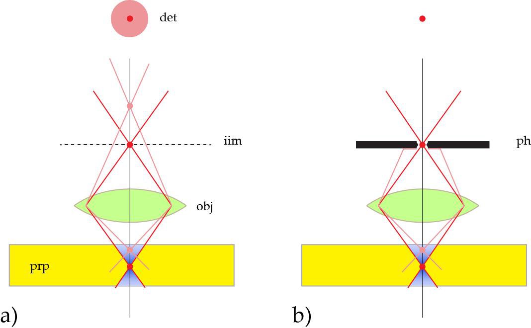
As illustrated in Figure 1 [3], the detection pinhole removes all emission not originating from the focal plane. It is therefore also referred to as “spatial filter”, filtering the depth of focus and blocking extrafocal signal. As the device cuts out sections from the sample by optical means, it is also called the “optical knife”.
Why is the pinhole’s diameter variable?
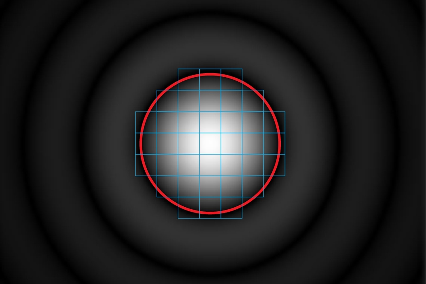
For general confocal imaging, the recommendation is to just transmit the inner part of the diffraction limited feature by the pinhole. This inner part is called the “Airy disc”. The size of Airy disc in the intermediate image depends on the wavelength (color), on the numerical aperture NA, the magnification of the objective lens and the magnification of internal optics of the microscope. The NA and objective magnification is engraved on the lens barrel. Consequently, the required pinhole diameter is different for various colors and for different objective lenses which have different NA and/or magnification.
In addition, a variable pinhole offers the freedom to the user to increase the optical sectioning sharpness by lessening the diameter or to reduce optical sectioning performance by increasing the diameter.
What happens, if the pinhole is larger?
As stated above, the pinhole for general confocal imaging should just pass the Airy disc. The diameter in this case is referred to as “Airy Unit, AU”. This is a good and practical compromise, not a law by nature. When the pinhole is increased, more and more extrafocal contributions will reach the sensor and increasingly fog the sharp focal information [4]. The overall intensity is thus increasing and apparently the signal to noise ratio (SNR) seems improving. But the increase is due to collecting unwanted blurry signal from layers outside the focal plane. If the pinhole is (virtually) infinity, the microscope behaves like a non-confocal widefield microscope (see Figure 3). It is therefore generally not recommended to open the pinhole just for the benefit to reduce the noisiness of the image.
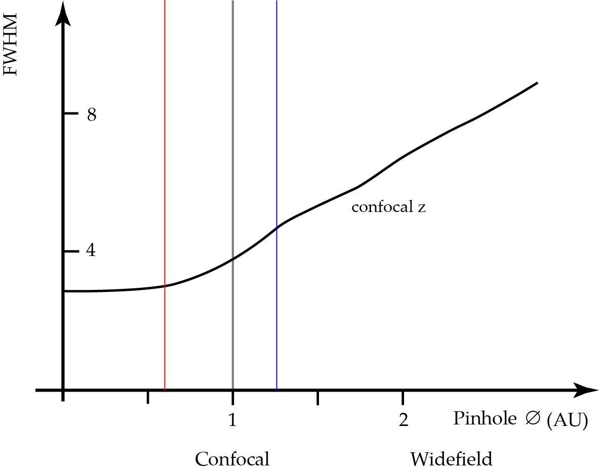
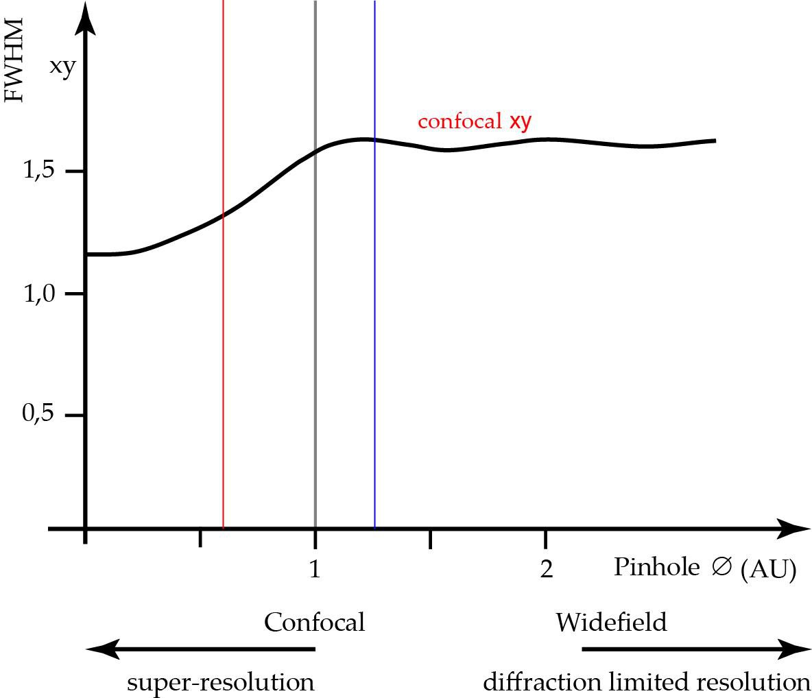
1 AU (grey vertical). When increasing the diameter, the detector will pick up extrafocal signal, the z-sectioning performance is deteriorated, although the intensity might increase. For pinhole diameters below 1 AU the sectioning performance will still increase, but assume a finite diffraction limited value at diameter zero.
The lateral resolution not affected and stays always at the value that is also true for widefield imaging and given by Abbe’s formula: d=λ/2NA (See Figure 4).
What happens, if the pinhole is smaller?
The thinnest optical slices, at the diffraction limit in axial direction, are obtained when the pinhole diameter assumes zero. This is, of course, not practical. As a matter of fact, the thickness of the slice at the diffraction limit is only 25% better [4] than at 1 AU.
Other than for pinhole diameters above 1 AU, also the lateral resolution is affected when the pinhole is closed. At pinhole zero, one can expect an increase in lateral resolution4 of ca. 30%. This improvement can be partially exploited by closing the pinhole somewhat below the recommended 1 AU. For example at 0,6 AU, we already gain 58% of the possible resolution increase. To still ensure good signal to noise ratio, we should use a microscope with very good efficiency for the emitted fluorescence and virtually noise-free sensors.
How does this relate to small fractions of psfs in image scanning?
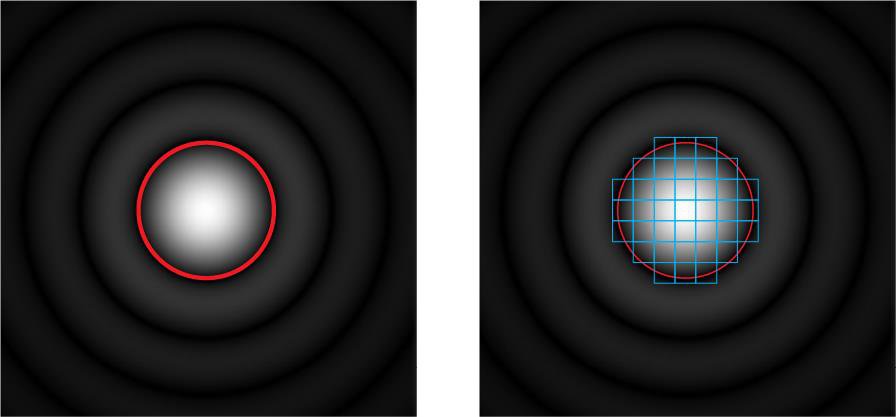
An alternative to closing the pinhole for increasing lateral resolution is a method, called “image rescanning” [5]. Here, the diffraction pattern itself is scanned again and the fractions are redistributed to neighbouring pixels (see Figure 2, right side). By computing a new synthetic image, the lateral resolution can be increased by about a factor of 1.4-fold as compared to widefield microscopy, nearly independent of the equivalent pinhole diameter. The optical sectioning performance, though, will assume the optical sectioning performance of the whole scanned area and follow the relations shown in Figure 3.
References
- Pinhole Camera (retrieved Feb. 21st 2017)
- C.J.R. Sheppard, A. Choudhury: Image Formation in the Scanning Microscope. In: Optica Acta: International Journal of Optics. 24, 1977, S. 1051–1073, doi:10.1080/713819421
- Borlinghaus RT: The White Confocal – Microscopic Optical Sectioning in all Colors. Springer International, Heidelberg (2017) ISBN 978-3-319-55561-4 (in press).
- Wilson T: Resolution and optical sectioning in the confocal microscope. Journal of Microscopy, Vol. 244, Pt 2 2011, pp. 113–121 doi: 10.1111/j.1365-2818.2011.03549.x
- de Luca GMR et al.: Re-scan confocal microscopy scanning twice for better resolution. Optics Express 4: 2644–56 (2013).
 and phalloidin (magenta), imaged using Viventis SCAPE; scale bar 50μm. Courtesy of Marina Cuenca and Heleen Jungen (Dayton lab), EMBL Barcelona.")
 and acceptor (A) molecule which participate in FRET (Förster resonance energy transfer).")