
Interference at gratings
To understand how an acousto-optical device works (at least in principle), we need to consider diffraction phenomena at periodic structures. The best known are gratings that are used widely in optics and optical instruments. Here a very brief recap: Two coherent waves can interfere. If they are in phase, the interference is constructive, i.e. the amplitudes will add up. If the phase difference is π (180°), the interference is destructive and the amplitude is zero if the incident waves have identical amplitudes. If a plane wave front interacts with a regular pattern (grid), each grid structure causes one spherical wave. All spherical waves interfere and generate a periodic pattern. This interference pattern is ruled by the distance of the grid elements d, the wavelength λ of the incident light, and the number of elements N that are illuminated. The size of the grid elements causes a modulation of the pattern (described by an envelope function).

Interference at three-dimensional lattices
Electromagnetic waves can also interact with elements of three-dimensional lattices. A well-known application is structural analysis by x-ray diffraction [1]. This is one of the major techniques that have helped scientists to understand the structure and function of proteins. X-ray crystallography is based on the fact that a wave that enters the crystal will interact with its constituents. Under fitting conditions, the wave will be deflected. For that to happen, the path difference of waves radiating from a lattice element must be a multiple of the wavelength. If this is the case, the waves are in phase and can interfere constructively. The Bragg condition [2] formulates this relation:
nλ = 2d sinα
See Figure 2 for explanation. In x-ray crystallography, a beam of x-rays is shone on the sample. Here, the elements of the lattice are atoms. As the wavelength has to be in the order of the size of the atoms, x-rays are a proper electromagnetic illumination source. The diffraction pattern is recorded after the rays pass through the sample. A sequence of patterns is recorded with varying angles, e.g. by rotating the sample. From that information, one can reconstruct the lattice structure, i.e. the composition and spatial arrangement of the atoms in the crystal.
.")
Refractive index grid – mechanical excitation by sound
To translate this phenomenon into the visible light regime, one needs much larger lattice constants (that is: the distance d of the layers). One possibility to generate such lattices is to induce mechanical waves in optical crystals. The mechanical wave causes the elements of the medium to exert a pattern of higher and lower densities, well known from the density patterns caused by an acoustic wave in the air. Consequently, such a lattice is made up by periodic variations of refractive index and hence called an refractive index grating [3]. The cycle of the mechanical (acoustic) wave depends on the frequency of the applied sound. To meet the conditions for visible light, the applied frequency is in the range of some hundred MHz.
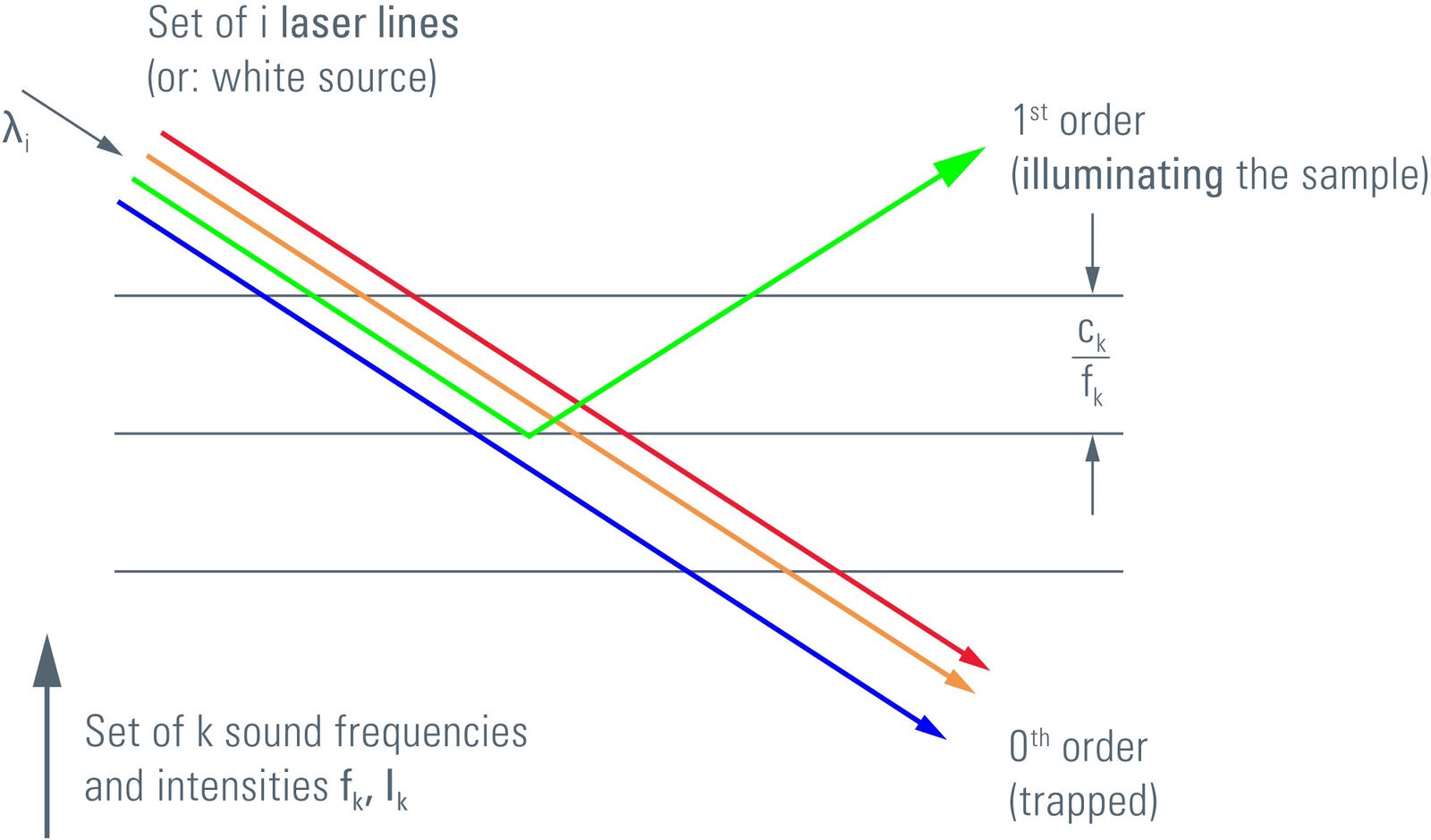
The interaction of light with acoustic waves (Brillouin scattering) is – as an approximation – comparable to the model shown above, if the light beam and the acoustic wave meet the Bragg condition.
As a matter of fact, the deflection occurs in two directions, +1st and –1st orders, with perpendicular polarization. For simplicity, we can omit the polarization effect in this context. The light sources in confocal microscopy are lasers and their derivatives which emit strongly polarized light. As a consequence, the –1st order is not populated and can be neglected here. The passing light (0th order) is of course polarization-independent.

Acousto-optical tunable filter
Light will only be diffracted into the first order if the Bragg condition is met. As the frequency of the sound wave is tunable, one can control which color of a composite light beam will enter the first order direction. All other colors will pass through the crystal unaltered and exit at the zeroth order. Furthermore, it is possible to superimpose a series of sound waves with different frequencies in order to collect a set of colors from the first-order direction. This allows single lines to be separated from a set of lasers, or – the more modern approach – tunable color bandlets to be selected from a white light laser source.
The efficiency of the acousto-optical effect is governed by the amplitude of the sound wave. With increasing energy of the sound wave, the fraction of diffracted light of the according color will increase until the full intensity is diffracted (saturation). This allows regulation of the intensity of the exit beam at the first order and hence the illumination intensity on the sample. Each color is individually attenuable.
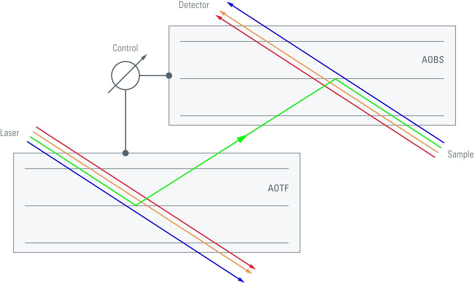
The two functions: color control by frequency and intensity control by amplitude for a series of colors are sufficient to create a multi-color tunable light source with independently dimmable intensities, which makes up an AOTF (acousto-optical tunable filter).
The sound wave is generated by a piezo element which is adhered to the acousto-optical crystal. To avoid scattering of the sound waves or generation of standing waves, an absorber is applied to the opposite side of the crystal.
The piezo element is driven by a power amplifier with controllable amplitude and frequency. Typically, the frequencies of the sound waves range from some 70 to 160 MHz. Each color requires a separate frequency; for simultaneous applications of a set of colors, a set of frequencies is generated and superimposed before being fed into the amplifier.
Acousto-optical beam splitter
The task to inject several colors for excitation of fluorochromes into the beam path with a tunable device is solved with the Acousto-Optical Beam Splitter (AOBS) [4]. In principle (but not in particular), it is an AOTF, operated in reverse mode. When the crystal is tuned to reflect the desired wavelength, one can also inject exactly that wavelength reversely from the first order direction. In this case, the optical axis is the non-diffracting path through the crystal. Hence, the excitation light will exit the crystal along the optical axis and can excite the fluorochromes. The emission, on the other hand, is Stokes-shifted, i.e. of different wavelength. Consequently, the emission will not exit at the first order, but simply pass through the crystal and exit along the optical axis. The emission light can then be fed into a spectral detector, e.g. the SP Detector from Leica Microsystems. As in this case the non-diffracting path is used, and the crystal is designed to have the excitation colors coming coaxially from the first order direction, the emission will be dispersed by diffraction. This has to be compensated for by appropriate measures. Hence, the AOBS is not simply an AOTF in reverse mode, but requires more design efforts and is more complex.
 from a laser battery or from a white light laser source into the optical path of a scanning microscope.")
Acousto-optical sinfonia
In classic systems, one has to select laser tubes, line selection filters and attenuation filters for excitation – and appropriate beam splitting mirrors that fit the selected excitation colors and the expected emission bands. This requires a large set of plan-optical filter devices and good knowledge of which beam splitting mirror should be activated for which excitation colors in combination with which set of fluorochromes. The combined acousto-optical solution with AOTF and AOBS [5] does not need any plan-optical device, but offers an infinite number of potential excitation lines on one side, and frees the operator from ruminating on which beam splitting mirror would fit best (also from accidentally using the wrong splitter!). The AOTF and AOBS are controlled synchronously by one single handle, which is the selector of the excitation color. That’s all there is to it. The rest is automatically set and adjusted by the microscope system.
This is a great advantage for systems equipped with laser batteries offering some 8 or so different laser lines. For systems equipped with a white light laser source, it is the only sensible design concept. The color(s) for excitation can be dialed from the white spectrum by the AOTF, and the injection of exactly these colors is assured automatically by the AOBS – with the emission transmitted unaltered and efficiently to the detection system. This is the only system that allows stepless scrolling through the spectrum for excitation. Consequently, if a white light laser source is employed, only an AOBS system can sensibly fulfill the task.
References
- Bragg WL: http://electrons.wikidot.com/x-ray-diffraction-and-bragg-s-law.
- Refractive index grating: http://en.wikipedia.org/wiki/Acousto-optics.
- Engelhardt J et al: Laserscanmikroskop. Patentschrift DE19944148 A1, filed Sep 15th, 1999.
- Borlinghaus RT: The White Confocal. Eur. Phys. J. Plus 127: 131 (2012); doi: 10.1140/epjp/i2012-12131-x.
 and phalloidin (magenta), imaged using Viventis SCAPE; scale bar 50μm. Courtesy of Marina Cuenca and Heleen Jungen (Dayton lab), EMBL Barcelona.")
 and acceptor (A) molecule which participate in FRET (Förster resonance energy transfer).")