
1. The vertical way – Confocal
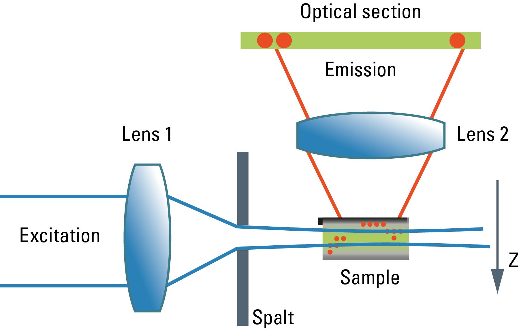
Most commonly, we have confocal microscopy [1] in mind when referring to optical sectioning. The confocal principle is seamlessly integrated into standard-type light microscopes (although the technical integration requires quite a bit of modification). Unlike ordinary light microscopy, true confocal imaging demands illumination of a single spot as tiny as possible. The spot’s diameter is ruled by wave optics and reaches a diffraction-limited minimum at d ≈ λ/NA. The detailed intensity distribution is described by the point-spread function. At the same time, the detector must also sense a spot as tiny as possible. As light paths are symmetrical, the same math applies to the sensing distribution of a point-like detector. The point detector is realized by introducing a pinhole aperture into an intermediate image plane in the detection path. In the sample, the foci of illumination and detection must coincide – hence "confocal" microscopy. As shown in Figure 1, the effect of this pinhole is the optical removal of all rays that do not originate from the focal plane. Its function is that of a spatial filter in z-direction.
As the optical knife works only on a single spot at a time, this spot must be moved in lines from top to bottom in order to generate an image. The intensity is synchronously converted into digital information and stored in a frame store on a computer. From this electronic memory, the image is displayed on an ordinary monitor. As the image must be constructed sequentially point by point, high frame rates are only possible under certain restrictions affecting the frame format and the accepted signal-to-noise ratio. Highly transparent beam paths, as for example the Leica SP detector, and very efficient sensors like hybrid detectors (HyDs) help to improve the high frame-rate performance. Meanwhile, line frequencies up to 12,000 Hz are implemented in confocal microscopes, compared to ca 15,000 Hz line frequency in PAL-standard television. Under appropriate conditions, frame rates of up to ca. 500 per second are possible. Nonetheless, to acquire a sufficiently high signal-to-noise image, frame rates will typically not exceed some 10 frames per second.
Another problem related to the scanning process is that areas of the sample above and below the focal plane are exposed to a high amount of illumination energy which does not contribute to the image but may cause photophysical degradation of fluorochromes. As fluorochromes absorb light also above the focal plane, the fluorescence intensity is increasingly dimmer when focusing deep into the sample. This may be compensated for by means of automatic gain adaptation, but at the cost of signal-to-noise.
The positive aspects of true confocal imaging are the high resolution (high-NA lenses are easily applied), the fact that the image is inherently homogeneous in the focal plane and that standard preparations are easily and effortlessly analyzed with confocal microscopes. Confocal microscopes are based on standard coaxial light microscopes, and all standard microscopy methods and contrast modes are accessible to the microscopist by a simple switch. It is also the base of other types of scanning microscopy, like multiphoton excitation, higher harmonic generation microscopy, coherent anti-Stokes Raman scattering microscopy and the super-resolution technique STED (stimulated emission depletion microscopy).

2. The horizontal way – Light Sheet
Although the confocal microscope is the gold standard for optical sectioning, the first microscope to perform this task was introduced half a century before. The "Spalt-Ultramikroskop" [2] used a bright light source (arc lamp or sun) which was focused into a slit aperture. A second lens, usually a reused objective lens, projected this slit into the specimen orthogonally to the optical axis of the microscope. This design effectively created a sheet-like illumination of some two micrometers thickness. The original application was concerned with sub-resolution particles, like dispersed gold in colored glass. It then proved useful for all kinds of colloidal samples and turbid media, which are commonly analyzed in chemical and medical research. This early light sheet microscope was restricted to visualize tiny particles down to 5 nanometers, which cause spherical scattering of the illumination that is observable as a diffraction pattern in the perpendicular beam path of the microscope. As a consequence, it visualized non-resolvable particles, called "Ultramikronen", which are "beyond the resolution of a microscope". The name "ultramicroscope" would suggest a superresolution type of design in the first place, but it was made plain by the authors that the ultramicroscope was clearly limited by optical diffraction.

Later, designs were developed that circumvented the precision slit and employed barrel lenses to create a sheet of light perpendicular to the optical axis [3]. This arrangement was then used for fluorescent, fixed samples. The light sheet microscope proved especially advantageous for fast live imaging of thick samples, as the bleaching is less pronounced and image recording is performed in parallel by a digital camera as shown by Huisken [6]. The absorption in z-direction is not an issue, as the illumination is equal in all positions in z on which the microscopist is focusing. However, the emission light has to pass the sample like in an ordinary microscope, which might deteriorate the image to some extent in thick samples. Still, there is a shadowing effect in the lateral direction: light is absorbed first on the side where the illumination light enters the sample, and thus the fluorescence is dimmed on the opposite side. Voie [3] compensated for this effect, by rotating the sample and collecting images from different orientations. Dodt [7] illuminated the sample from two opposite sides to compensate for absorption of the light sheet. Instead of using a projected slit aperture or a cylindrical lens, Keller [4] scanned a thin laser beam perpendicular to the observation axis. This scheme was called "Digitally scanned light sheet".
3. The conjunction

Both paradigms have been introduced in biomedical research and routine, serving for many new insights and understandings of biological concepts and diseases, and of the construction and function of cellular components. In terms of instrumentation, the two ways are significantly different, the orthogonal illumination was treated as a separate part of the system and combined with a coaxial microscope in order to perform the task. The confocal microscope uses a beam-scanning system to create twodimensional images, the digitally scanned light sheet uses beam scanning to create areas from lines. This immediately raises the question of whether it would be possible to combine both strategies in a single system. Leica Microsystems provides this solution with the STELLARIS DLS light sheet microscope [5].
The STELLARIS DLS is based on an ordinary confocal microscope, a coaxial scanning device that performs optical sectioning by spatially filtering the out-of-focus light by virtue of a detection pinhole. Images are generated by means of galvanometric scanning mirrors that move the illumination spot in the two lateral directions. To convert such a system into a digital light sheet microscope, one must make the illumination beam pass through the sample perpendicular to the optical axis. By introducing a small mirror at the position of the focal plane, just outside the observed field, the required orthogonal illumination is achieved. Such a deflecting mirror is mechanically connected to the observation lens to ensure the illuminated z-position is always in the focus of the image-generating optics, while the image is projected onto a video camera that converts the intensities into a digital image.
A single position of the illumination beam would not cause a two-dimensional image, but only a single line. One can make use of one of the lateral scanning modes inherently implemented in a confocal microscope to scan the illumination line in the perpendicular direction, yielding the required two-dimensional plane.
If a second mirror is introduced on the opposite side, it is possible to illuminate the sample from two sides through the same lens – just by employing the second axis of the beam-scanning device of the confocal microscope. This fulfills the need to compensate for absorption-caused shadowing. The final image is then again constructed from the two images with different illumination directions.
For imaging in confocal mode, the z-drive mechanism has to be positioned so that the focus of the illumination beam coincides with the feature that is to be imaged. The scan process then covers just the inside of the field of view, which is the common way to operate a confocal microscope. To switch to light sheet acquisition, the focus has to be moved by about the distance of the mirror to the optical axis. In this case, the plane-generating part of the illumination beam will fall into the center of the observation field. The scanning device needs to point to the edge of the field of view in order to hit the mirror.
This combination does not only reduce instrumentation cost, as two different instruments are merged into one, but it also allows the combination of classical confocal and light sheet microscopy. As a consequence, the same system allows any sample to be explored with the technique that is most suitable to address the current research question. It also enables a variety of new application opportunities since the confocal path could be used for photo-manipulations with subsequent gentle light sheet imaging of the induced effects.
References
- Minsky M: Microscopy Apparatus. US Patent 3.013.467, filed 7th November 1957, granted 19th December 1961 (1961).
- Siedentopf H, and Zsigmondy R: Über Sichtbarmachung und Größenbestimmung ultramikroskopischer Teilchen, mit besonderer Anwendung auf Goldrubingläser. Ann. Phys. IV (10): 1–39 (1903).
- Voie AH, Burns DH, and Spelman FA: Orthogonal-plane fluorescence optical sectioning: three-dimensional imaging of macroscopic biological specimens. J. Microscopy 170 (3): 220–36 (1993).
- Keller PJ et al.: Reconstruction of Zebrafish Early Embryonic Development by Scanned Light Sheet Microscopy. Science 322: 1065 (2008).
- Knebel W, and Sieckmann F: Verfahren und Anordnung zur Beleuchtung einer Probe. German patent application, publication Nr. DE 10 2011 054 914 A1 (2011).
- Huisken J et al.: Optical sectioning deep inside live embryos by selective plane illumination microscopy. Science 305 (5686): 1007–9 (2004).
- Dodt HU et al.: Ultramicroscopy: three-dimensional visualization of neuronal networks in the whole mouse brain. Nat. Methods 4 (4): 331–36 (2007).

 and astrocytes (green) in a cortical spheroid derived from human induced pluripotent stem cells.")
.")
