Large field of view and high magnification
In patch clamp experiments a tight seal is formed between a glass pipette and the cell membrane. This arrangement allows the recording of small currents and voltages involved in the activity of neurons and other cells (Figure 1). A large observation field is necessary in order to find the regions of interest within a specimen, for example in the brain of a living mouse, living brain slices, embryos, etc. In addition, it is important to be able to visualise detailed structures so that pipettes and electrodes in the specimen can be placed accurately.
The Leica DM6000 CFS combines the new high NA/low magnification objective lens HC X APO L20x/1.0 W with the magnification changer in the CCD camera mode. This combination allows for a fast overview of the specimen while keeping a large observation field. Furthermore, the observation field can be changed easily by using different magnification changers. A large field of view is achieved using the 20x objective. To identify individual cells, the 4x magnification changer can be used. Therefore, using both the objective and the magnification changer it is possible to easily position pipettes very close to the cell (Figure 2). If a higher resolution is required, as for the investigation of neuronal spines, the system can be switched to confocal scan mode.
Single cell electroporation
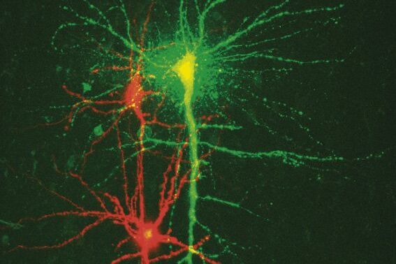
To study neuronal networks in the brain, specific labelling of individual cells is required. A new method, called single cell electroporation (Nevianand Helmchen 2007), allows rapid and selective loading of cells. Brief voltage pulses are delivered, causing an electromagnetic field to be applied to the membrane. This results in the transient formation of small pores; the pores close within seconds. Charged molecules are transported in the direction of the electrochemical gradient during opening of the pores. This method can be used to load neurons with calcium-sensitive dyes and other dyes (Figure 3).
Using the single cell electroporation technique, the background staining is lower compared to using the loading by intracellular recording electrodes or patch pipettes. The single cell electroporation technique is especially well suited for functional imaging of subcellular Ca2+-dynamics in vitro and in vivo. Multiple substances can be loaded to obtain morphological and functional measurements at the same time. Furthermore, multiple cells can be loaded sequentially in order to image small neuronal networks by using the same pipette.
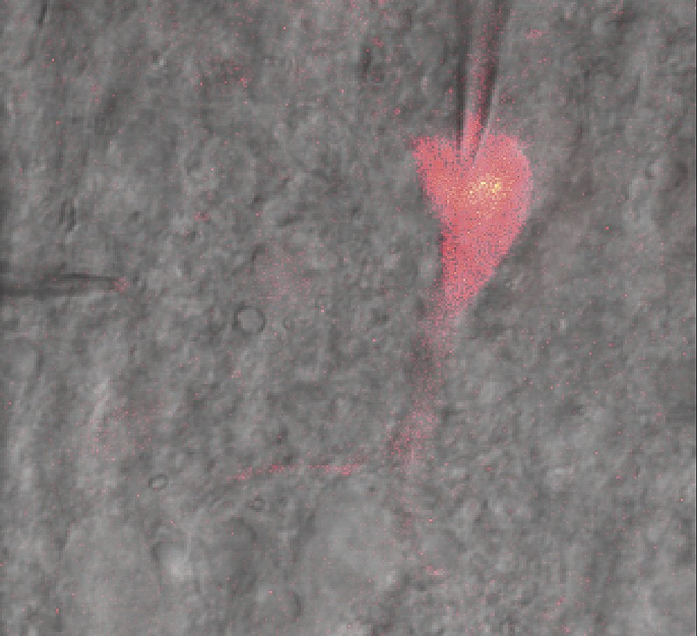
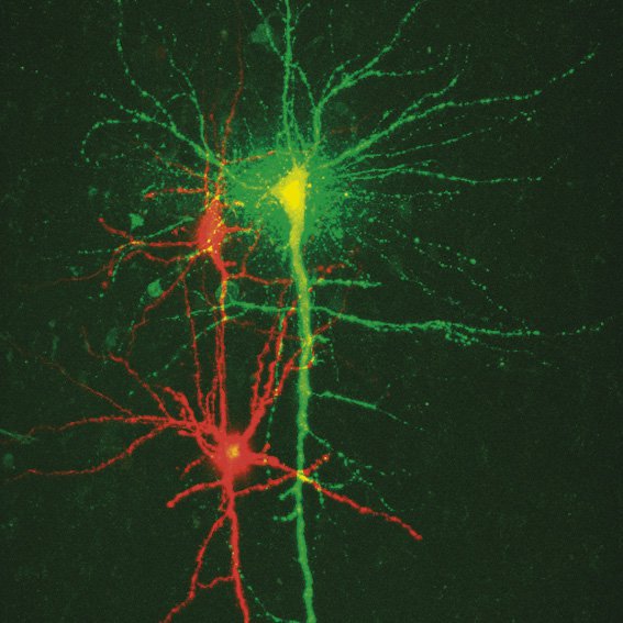
Fig. 3: a) A specific neuron was loaded with a calcium sensitive dye by single cell electroporation; overlay of simultaneous acquisition of fluorescence with a Non- Descanned Detector (NDD ) and transmitted light; b) small neuronal network: rat brain slice, layer 5, red: Interneurons Alexa 594, green: Pyramidal Cell Oregon Green Bapta 1 (calcium sensitive), Z = 123 μm, two photon excitation; detection with a 2-channel NDD. Courtesy of Dr. Thomas Nevian, Inst. of Physiology, University of Bern, Switzerland.
Correlating optical and electrical data – and images
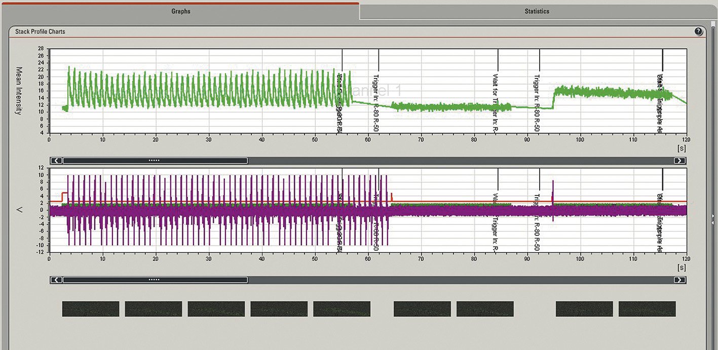
In many physiological applications the reaction of cells to different types of stimuli is of interest. The reactions of the cells, as seen by electrical and fluorescence intensity data, need to be measured and displayed in a synchronised manner. The intensity data usually refer to the intracellular calcium concentration or pH-value. The Leica DM6000 CFS enables the synchronised correlation of electrical and optical data; voltage recordings are correlated in synchronisation with the fluorescence intensity data and are automatically displayed in graphs. This reveals a fast and direct overview of the experimental progress and online data evaluation. Furthermore, images are displayed below the graphs to get fast information about the morphology of the cell.
A data acquisition box and Leica trigger unit are integral components for viewing the intensity and voltage data correlation. Recorded signals, as from a neuron, are typically amplified, and then sent to a NI Data Acquisition Box (DAQ box) from National Instruments, which digitises the signals. The DAQ box is connected to the trigger unit that allows for the synchronisation with the scanning process. It is also connected to the PC so that correlated optical and electrical data, as well as images, can be displayed.
Currents and calcium in heart muscle cells
With the calcium-sensitive dye Fluo4 labelled isolated cardiomyocytes from trout were stimulated by a trigger pulsing regime using patch clamping (HEKA EPC –10 double). Cardiomyocyte responses to intracellular calcium concentration and ionic currents were measured using fluorescence imaging and electrical recordings. The stimulation protocol on the patch clamp setup was synchronised with the confocal time lapse series using a trigger on the patch clamp setup to mark events in individual frames on the time axis. Line triggers are recorded in order to have the exact correlation of the image scan, fluorescence signal intensity, and electrical response of the cell (Figure 4). These triggers are automatically generated by the scan head. This means that whenever a line is scanned, its corresponding trigger pulse is recorded and displayed in the quantification chart. Synchronisation of images and triggered pulses is accomplished using the Leica DAQ box.
Multiphoton microscopy and externaldetectors
A major challenge in physiological applications is the study of cells in deeper layers of tissue. Multiphotonmicroscopy provides several advantages for solving this challenge. Lower light scattering, restricted excitation and bleaching to the focal plane, and reduced phototoxicity are the properties of multiphoton microscopy that enable visualisation of deep structures. Brain slices, for example, are highly scattering and are usually sliced several hundred micrometres thick. Therefore it is very difficult to image brain slices using a standard confocal microscope. Thicker specimens can be imaged using multiphoton microscopy due to an enhancement in photon collecting efficiency.
In confocal microscopy the pinhole aperture rejects the out-of-focus fluorescence light as well as the scattered (diffused) light. Since the scattered lightis not ‘seen’ by the detector, it is not easy to image highly light scattering tissues such as thick brain slices. In multiphoton microscopy however, no confocal pinhole is required to reject the out-of-focus light because all fluorescent light originates from the focal spot. The emitted light from the specimen does not need to pass through the microscope again. Therefore, detectors can be placed as close as possible to the specimen so that scattered photons can be collected. In this way significantly higher photo ncollection efficiency is achieved compared to confocal microscopy.
The external Non-Descanned Detectors (NDDs) are PMT s for collecting emitted light from the focused and scattered light (Figure 5). The NDDs are boxes containing PMTs for the detection of either two or four different fluorescence signals (4-channel NDD). To separate the signals, several filter cubes are available and can be introduced into the detector box.
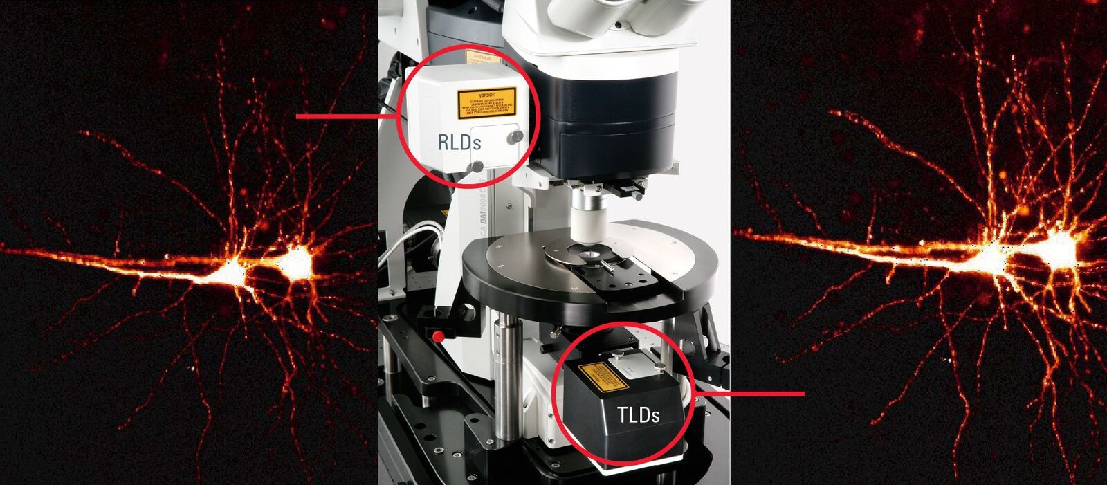
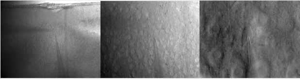
Fig. 5: A Leica DM6000 CFS System equipped with external detectors (NDDs). Images: Neurons selectively marked in a 300 μm thick living mouse brain section excited with IR light. Two neurons in a living brain slice labelled with Oregon Green Bapta 1. Detection of the same fluorecenceby RLD and TLD. The TLD shows a significantly brighter signal. Courtesy of Dr. Thomas Nevian, Inst. of Physiology, University of Bern, Switzerland.
Fluorescence and high contrast transmitted light imaging
Unstained neurons in thick brain slices are phase objects. To make them visible it is necessary to convert their phase gradients into amplitude gradients. There are different ways to achieve this. One is by using differential interference contrast (DIC), which requires prisms and polarisation filters in the beam path. Thus, when transmitted light and fluorescence are imaged together the photon collecting efficiency is reduced due to the optical components in the beam path.
Infrared Scanning Gradient Contrast (SGC imaging) – also referred to as Dodt Contrast – is another method used to visualise unstained cells in thick scattering tissue. This is a special optical system developed by Hans-Ulrich Dodt (Max-Planck Institute, Munich, Germany). In this technique the contrast can be specifically adjusted to enable different structures (horizontal or vertical) to be highlighted.
Using the Dodt gradient contrast method no optical components are needed in the beam path to get high-contrast and high-resolution images. Here, a lens system between the microscope stage and the lamphouse re-images the aperture plane of the condenser. Spatial filtering is performed by a quarter annulus located in the illumination beam. After the annulus, a diffuser is placed to generate an oblique illumination across the condenser aperture. The light-stop blocks much of the illuminating light and only a part of the illuminating light cone is used. Therefore, less straylight is generated in the slice and an oil-immersion condenser, e.g. with 1.4 NA, can be used for high resolution images. Adjustments can be made to the direction of the spatial filter and to the distance of the diffuser with respect to the spatial filter.
The contrast created is very strong and images look similar to DIC images. The Dodt gradient contrast images are detected with a transmitted light detector or so called Dodt detector. The PMT of the Dodt detector has a higher IR-sensitivity (up to approx.900 nm) compared to regular PMTs. A Leica DM6000 CFS system equipped with NDDs and a Dodt detector allows simultaneous detection of fluorescence and transmitted light when using IR excitation. It provides the highest photon collection efficiency as there are no optical components in the beam path. This also facilitates many applications in physiology, e.g. optically guided patch clamping (Figure 6). The NDDs are also suitable for detection of second harmonic generation signals (SHG ) (Figure 7). The Dodt gradient contrast works in camera and scanning mode when using IR excitation. It can also be used upon VIS excitation, but the contrasting effect can be less prominent.
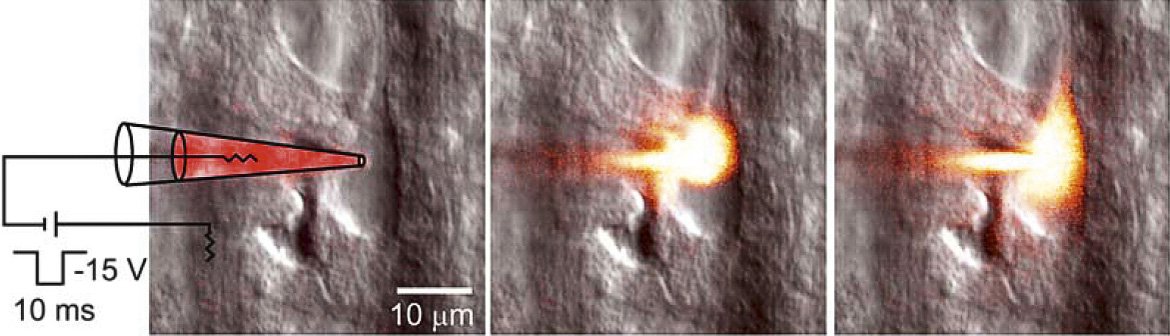
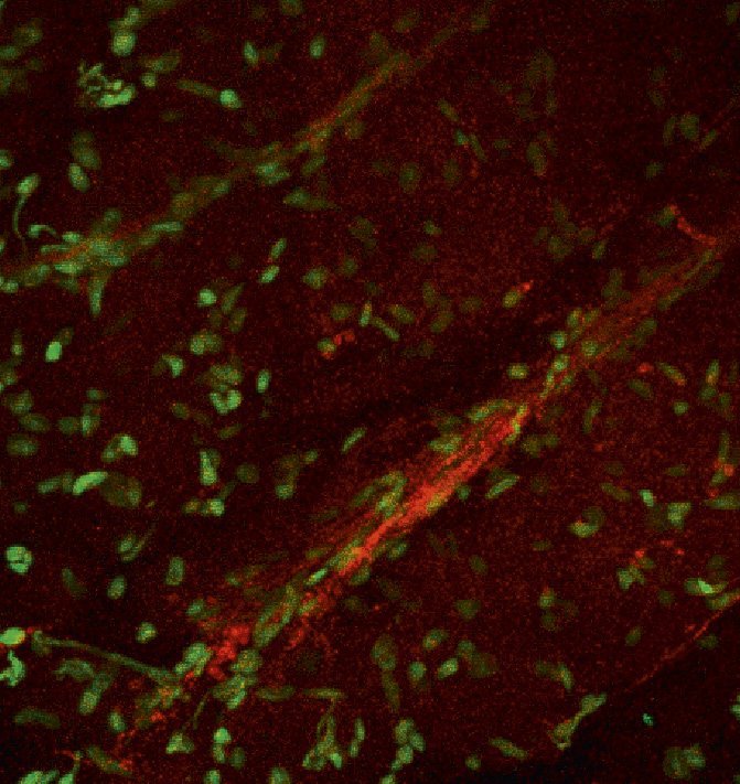
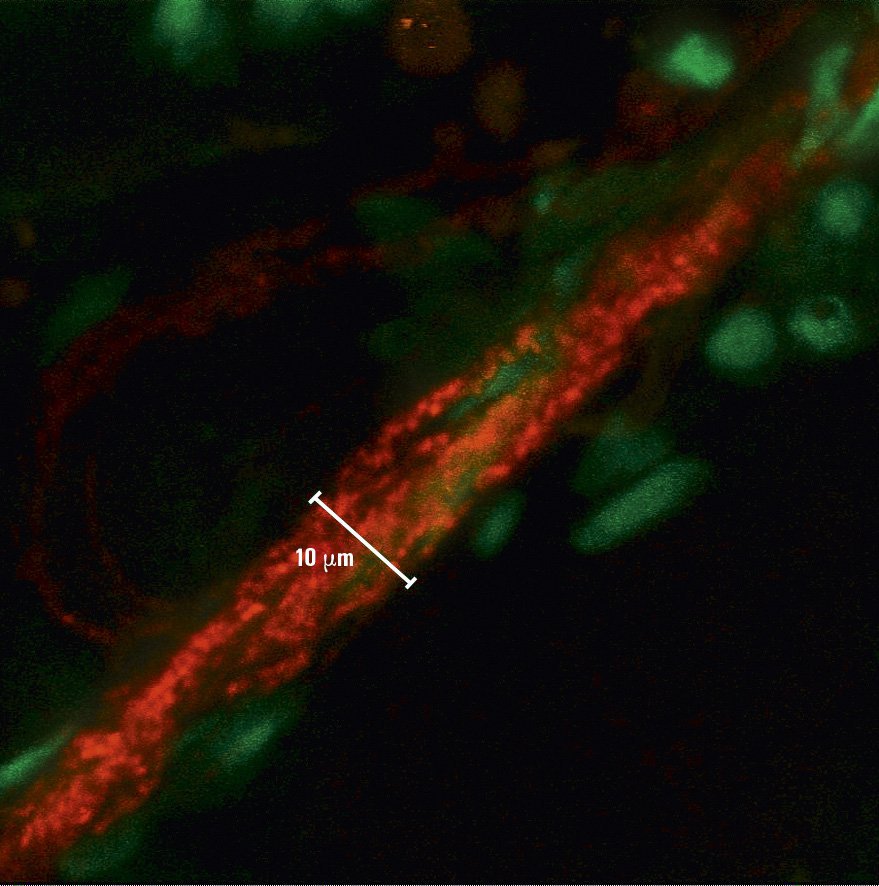
Fig. 7: The mouse heart was excised and a 2 % agarose gel was subsequently cast around a 1 mm thick slice of the organ. Two-photon excitation was used with 840 nm. Fluorescent labelling of cell nuclei was done with Syto13 (green). Left: Overview image, cell nuclei of cardiomyocytes are visible. The "threads" of nuclei belong to endothelial cells in the capillaries around the cardiomyocytes. In red the second harmonic generation signal of collagen in the capillaries is visible. The vague reddish background is auto-fluorescence of the cardiomyocytes. Right: Zoomed image, second harmonic generation signal of collagen and its association with endothelial cells is more clearly visible. Courtesy of Dr. Marc van Zandvoort, Biophysics, Univ. of Maastricht, Netherlands.


 at 2 weeks. Image acquired using Mica.")
