Low angle rotary shadowing
With the new generation of EM ACE600 e-beam evaporators it is possible to produce homogeneous, very thin and low grained electron-transparent carbon layers to be used as supports to adsorb biological objects including DNA molecules, proteins or DNA-protein complexes. Single Molecules, or macro-molecular complexes absorbed on the thin carbon layer are then shadowed using a precise and reproducible shadowing angle leading to high contrast TEM images. The protocol applied in this article focuses on the use of e-beam evaporation in the visualisation of DNA molecules and has been initially set up by Dr. José Sogo’s laboratory at the ETH institute of Zurich and subsequently implemented, improved and made available to the scientific community by the Prof. Massimo Lopes’s laboratory at the IMCR institute of the university of Zurich[1]. Since the details of this procedure have been recently updated [1], we will briefly refer to the key steps of the protocol adding experimental details specifically related to the use of the EM ACE600 coater in the contest of this well-defined and tried experimental workflow.
Key steps of the procedure, advantages and requirements on the DNA sample
This protocol applies to purified DNA molecules. DNA samples suitable for this procedure must be completely free of proteins and RNA molecules. With this technique it is possible to distinguish the difference between double strand (ds) DNA and single strand (ss) DNA based on the different thickness of the two forms of the DNA fibre (see next paragraphs).
First step of the protocol
A balanced mix of DNA molecules in solution is created with formamide and the detergent benzyl-dimethyl-alkyl-ammonium chloride (BAC). This mix is spread on a big surface of water with a specific spreading procedure.
Second step of the protocol
The mono-molecular film of DNA molecules is touched with a 400-mesh copper TEM grid on which a thin (4-8 nm), homogeneous and low grain carbon layer is deposited (see next paragraph). The TEM grid is then immediately submerged into a solution of ethanol and uranyl acetate.
Third step of the protocol
The carbon grid with absorbed DNA molecules is subjected to a precise low angle rotary shadowing with 8 nm of platinum. This is a negative staining, which will be specifically effective for the visualization of the ds DNA fibre.
Settings of EM ACE600 to produce high quality carbon layers
The combination of high quality carbon layers and precise low angle rotary shadowing with platinum results in high quality TEM images of DNA fibres (see Results). In the procedure described here, the carbon layer is created with the EM ACE600 coater on a V2 high grade Mica sheet, is then floated on the surface of the water and, finally, deposited on 400 mesh copper grids without any additional layer of formvar or other support material. Carbon surfaces created with this procedure have high efficiency in the absorption of DNA molecules and do not need to be glow discharged.
Low angel rotary shadowing with Platinum - Operation and settings of the EM ACE600 coater
DNA molecules absorbed on the carbon surface of a 400 mesh copper grid are subjected to precise low angle rotary shadowing with 8nm of platinum. The grids are fixed on the GRID stage for low angle rotary shadowing of EM ACE600. In this case two different processes have been designed and are run in sequence. In the first process the surface of the carbon on the grid is covered with 0.4 nm of platinum at a coating angle of 1° without rotation of the GRID stage. In the second process 7.6 nm of platinum are deposited with the same coating angle but with the rotation speed of the GRID stage set at level 1.
Hints and consideration to optimize results
It is very important to set the evaporation parameters (principally the evaporation power) the way that the evaporation speed is kept at a cons¬tant value (0.03-0.08 nm/second) both for the production of the carbon layer and for the low angle rotary shadowing with platinum. In order to create high quality and low grain metal layers, the e-beam guns and the evaporation chamber must be kept extremely clean.
Advantage of the new generation of e-beam coaters
The new generation of EM ACE e-beam coaters has several improvements compared to the previous MED generation of evaporators. The robustness of the new components of the coater makes the difference. The design of the e-beam guns and the updated electronics with the possibility to have a digital view of all parameters on a touch screen display are a big advantage. Also, the presence of safety feedbacks, which do not allow the evaporation if tension and current parameters exceed certain values, will help to preserve the machine and to work in safer conditions.
Regarding the specific application described here, which implies the utilisation of a very precise and reproducible shadowing angle, the presence of a sophisticated motorized stage, which is controlled digitally via the touch screen, should be highlighted. Last but not least, all parameters of the single runs and the designed processes can be stored, retrieved and put into a sequence with a very intuitive interface, which allows also non-experienced users to work with the machine.
Results
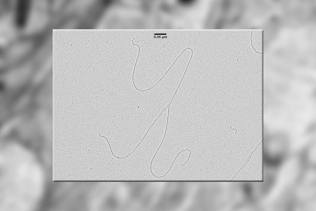
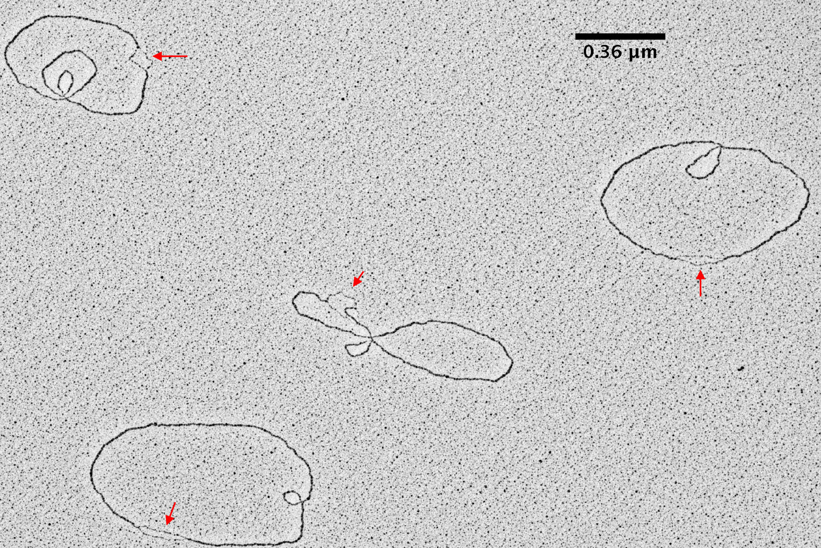
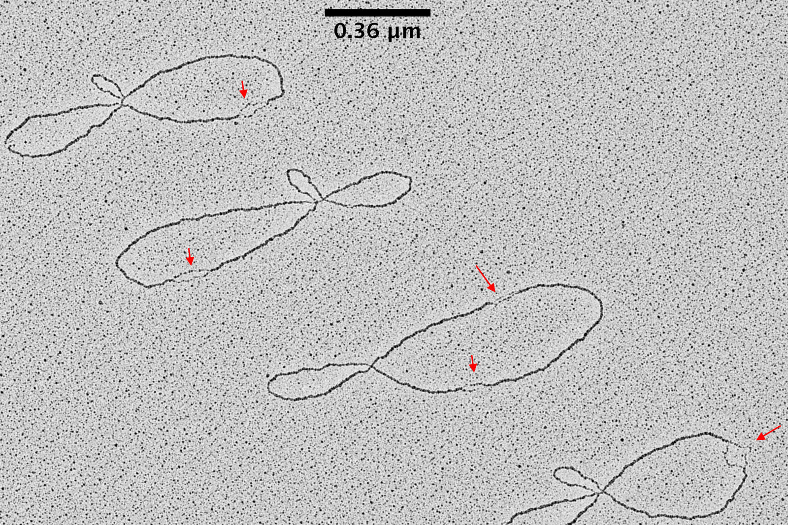
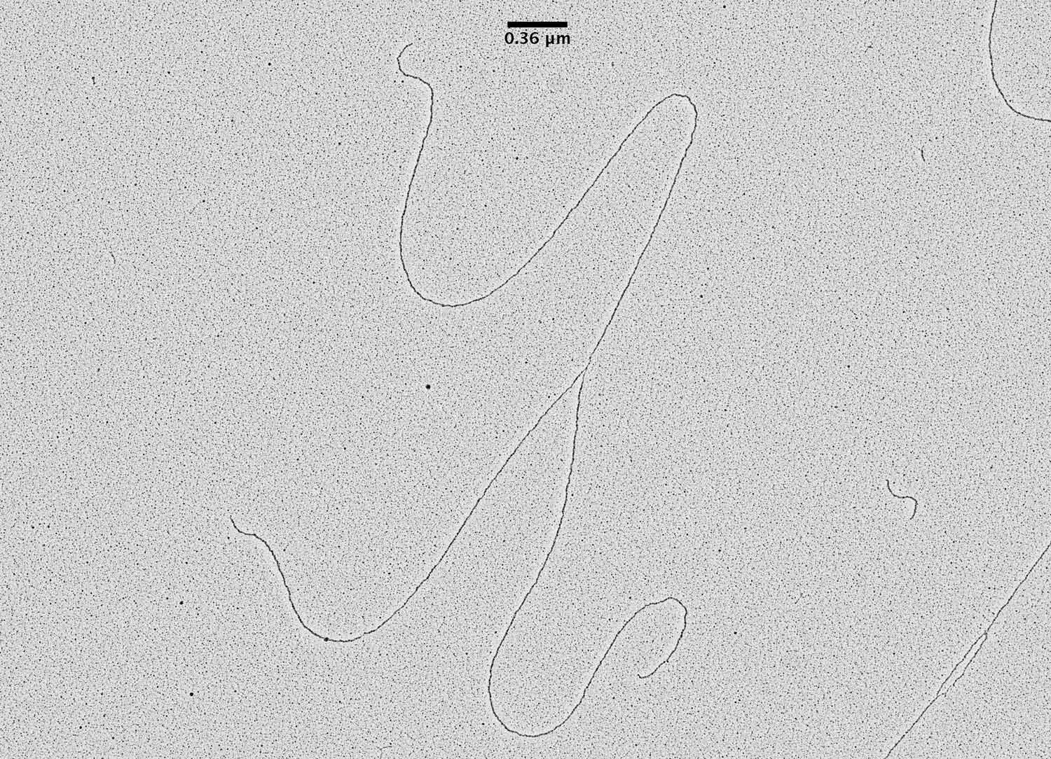
TEM pictures of plasmid DNA molecules in solution visualized using BAC spreading, uranyl acetate staining and low angle rotatory shadowing with the EM ACE600 e-beam coater. A scale bar (which correspond roughly to 1 kilo base of DNA) is reported in black. Red arrows indicate regions of the plasmid molecules that are under-wound and have the intrinsic tendency to get denaturated in this experimental condition. These images clearly show that this technique allows to distinguish the difference between ss DNA and ds DNA. With this technique the thickness of the ds DNA fibre is around 20 A°. In this experimental condition 0,36 nm corresponds, roughly, to 1bp of ds DNA. The picture has been taken using a FEI Tecnai12 bio-twin microscope operated at 80 KV and equipped with a side mounted Gatan Orius SC-1000 camera controlled by Digital Micrograph Software.
Download PDF
Related Articles
-
-b-poly(isoprene). Right: Poly(styrene)-b-poly(methyl methacrylate).")
Ultramicrotome Sectioning of Polymers for TEM Analysis
We demonstrate the capabilities of the UC Enuity ultramicrotome from Leica Microsystems for…
Sep 30, 2025Read article -

Integrated Serial Sectioning and Cryo-EM Workflows for 3D Biological Imaging
This on-demand webinar explores how integrated tools can support electron microscopy workflows from…
Jul 22, 2025Read article -

The “Waffle Method”: High-Pressure Freeze Complex Samples
This article describes the advantages of a special high pressure freezing method, the so-called…
Jul 08, 2025Read article
