
Magnification of digital microscopy
Basic definition
What exactly is magnification? A basic definition of magnification is the ratio of the size of a specific feature of an object or sample as seen in an image produced by an optical system to the actual size of the feature on the object itself. Thus, lateral magnification, MDIS, can be defined as:

It should be noted that the useful range of perceived visual magnification significantly depends on the maximum resolving power of the microscope system. When the magnification passes beyond the useful range, then no additional details about the sample can be seen. This situation is referred to as empty magnification [13]. Based on the maximum resolving power, also a useful range for the viewing distance, i.e. the distance between the digital display and the observer’s eyes, can be defined for practical reasons.
Digital microscopes or stereo microscopes with digital camera
When observing the image through the eyepieces of a stereo microscope, the total (lateral) magnification is defined as [8]:

where
- MTOT VIS is the total lateral magnification observed through the eyepiece,
- MO is the objective lens magnification,
- q is the total tube factor (zoom and other tube lenses), and
- ME = eyepiece lens magnification.
For the case of detecting an image of a microscope which is projected onto an electronic sensor, such as that of a digital camera, the magnification for the image formed at the sensor is [8]:


where
- MTOT PROJ is the (lateral) magnification of the microscope (image projected onto sensor),
- p is the projection factor from eyepiece to camera, and
- MPHOT is the magnification of the photographic projection lens from the tube to camera.
The total tube factor, q, is normally between 0.5x and 25x. The photographic projection lens magnification, MPHOT, is normally between 0.32x and 1.6x.
For digital microscopes, there are no eyepieces, so an image is projected onto and detected by an electronic sensor of a digital camera, and then displayed onto an electronic monitor for observation. This fact is also true for a stereo microscope equipped with a digital camera when the image is observed via the monitor. Thus, the final total magnification for digital microscopy, MDIS, will always depend on the size of the image displayed on the monitor. For this report, a display of the image from the camera sensor to the monitor is assumed to occur in a 1-to-1 pixel correspondence mode, the simplest case scenario. The signal from one pixel of the camera is displayed on one pixel of the monitor. Thus, the ratio of the monitor to camera sensor image size is directly proportional to the actual pixel size of the monitor and sensor (refer to the Appendix below for more details). It can be defined as:

where MDIS is the total lateral display magnification for an image displayed on a monitor and the pixel size ratio is the "enlargement" of the image due to the signal transmission of the image from the camera to the electronic monitor display.
The pixel size ratio is determined by the ratio of the pixel size of the monitor to that of the camera sensor:

As already mentioned above, a 1-to-1 pixel correspondence mode is assumed for image display from the camera sensor to the monitor. In this display mode, depending on the monitor’s number of pixels, only a portion of the image may be visible on the monitor.
Examples of digital microscopy are shown in Figure 1: a digital microscope and stereo microscope with digital camera.

Resolution
For optical instruments in general, resolution is the ability to see fine details in an image. More specifically, resolving power is the ability to distinguish in an image adjacent points or lines of the object which are closely spaced together. Usually these two terms are used synonymously, however resolution is the more practical one. In microscopy, resolution is expressed in line pairs per millimeter. In other words, pairs of black and white lines with equal line thickness and spacing can be distinguished at a given resolution.
High-magnification values without sufficient resolution lead to empty magnification, as already mentioned above [13]. Therefore, it is of vital importance to understand the limiting factors for resolution, not just for digital microscopy, but all forms of optical microscopy.
Camera sensor and display monitor pixel number and size
The sensors used in all Leica digital microscope cameras have a number of pixels typically between 3,072 × 2,048 and 5,472 × 3,648 and a pixel size between 1.55 and 2.4 μm (examples in Table 1). Ultrahigh-definition (UHD/4k) computer monitors or televisions have 3,840 x 2,160 pixels and full-high-definition (FHD+ or FHD) ones have 1,920 × 1,200 or 1,080 pixels. Pixel sizes are between 0.1 and 0.5 mm (examples in Table 2) [14,15]. Therefore, the monitor pixels are typically 40 to 325 times bigger than the camera pixels (examples in Table 3).
Camera | Sensor type | Diagonal (mm) | Width (mm) | Height (mm) | Pixel size (mm) | Pixels | Megapixels |
| K3C | 1/1.8“ “ | 8.92 | 7.42 | 4.95 | 2.4 | 3,072 x 2,048 | 6.29 |
| Flexacam c5 & i5 / Emspira 3 / Ivesta 3 (integrated camera) | 1/2.3“ | 7.81 | 6.25 | 4.69 | 1.55 | 4,000 x 3,000 | 12 |
| K5C | 1” | 15.86 | 13.2 | 8.8 | 2.4 | 5,472 x 3,648 | 19.96 |
Table 1: Specifications of image sensors used in the Flexacam c5 and i5, K3C, and K5C digital cameras, Emspira 3 digital microscope, and Ivesta 3 stereo microscope with integrated camera supplied by Leica Microsystems.
| HD flat display | Width (mm) | Height (mm) | Pixel size (mm) | Pixels | Megapixels |
|---|---|---|---|---|---|
| PC monitor 21.5'' | 476 | 267 | 0.25 | 1,920 × 1,080 | 2.07 |
| PC monitor 24'' | 531 or 521 | 299 or 324 | 0.14 or 0.27 | 3,840 × 2,160 or 1,920 × 1,200 | 8.29 or 2.3 |
| PC monitor 27'' | 597 | 337 | 0.16 or 0.31 | 3,840 × 2,160 or 1,920 × 1,080 | 8.29 or 2.07 |
| PC monitor 32'' | 708 | 398 | 0.18 or 0.36 | ||
| PC monitor 43'' | 952 | 535 | 0.25 or 0.49 | ||
| PC monitor 55'' | 1,218 | 685 | 0.32 | 3,840 × 2,160 | 8.29 |
| TV 65'' | 1,439 | 809 | 0.37 | ||
| TV 75'' | 1,660 | 934 | 0.43 | ||
| TV 85'' | 1,882 | 1,059 | 0.49 | ||
| TV 98'' | 2,170 | 1,220 | 0.56 |
Table 2: Examples of UHD/4k (3,840 x 2,160 pixels), FHD (1,920 x 1,080 pixels), and FHD+ (1,920 x 1,200) electronic monitor displays: computer (PC) monitors or TVs.
Pixel size ratio
From knowing the typical pixel sizes of the camera sensors (Table 1) and flat screen UHD monitors (Table 2), then values for the size ratios can be easily calculated using Equation 5 (Table 3).
| Camera type | Monitor size (inch) | ||||||||
| 98” | 85” | 75” | 65” | 43” | 32” | 27” | 24” | 21.5” | |
| Pixel size ratio | |||||||||
| Flexacam / Emspira / Ivesta | 361:1 | 316:1 | 277:1 | 239:1 | 161:1 | 116:1 | 103:1 | 90:1 | 161:1 (no binning) |
| K3C / K5C | 233:1 | 204:1 | 179:1 | 154:1 | 104:1 | 75:1 | 67:1 | 58:1 | 104:1 (no binning) |
Table 3: Pixel size ratios (Equation 5) for UHD or FHD (21.5” only) monitors (Table 2) and sensors used in the Emspira 3 digital microscope, Ivesta 3 stereo microscope with integrated camera, and Flexacam, K3C, and K5C digital cameras (Table 1).
Examples: Digital microscope and stereo microscope with digital camera
For simplicity, only 2 examples of digital microscopy, actually a digital microscope and a stereo microscope equipped with a digital camera, will be discussed in this report. It is assumed that an image is displayed, using a 1-to-1 camera to monitor pixel correspondence, onto a UHD or FHD monitor with sizes ranging from 21.5'' (diagonal dimension 21.5 inches [54.6 cm]) to 75'' (diagonal dimension 74.5 inches [189 cm]). It is also assumed that the cameras display the image with a UHD format. For a FHD monitor (21.5"), then a camera-pixel binning of 2x2 (refer to figure 2) must be used, meaning that the pixel size doubles and pixel size ratio is cut in half. The 2 examples are the Emspira 3 digital microscope and the M205 A stereo microscope having the Flexacam c5 digital camera installed with a C-mount. Table 4 shows examples of total magnification (refer to Equations 2 and 4) values obtainable with the Emspira 3 or M205 A microscope equipped with the Flexacam c5 camera. For the Emspira 3 microscope, the magnification range for the objective lens is 0.32x to 5x and for the zoom 0.75x to 6x (tube factor, q, including the photographic projection lens has an 8:1 range from highest to smallest magnification). For the M205 A microscope with Flexacam c5 camera, the magnification range for the objective is 0.5x to 2x, for the zoom 0.78x to 16x, for the eyepieces 10x to 25x, and for the C-mount lens 0.4x to 1x.
| Emspira 3 | M205 A/Flexacam c5 | ||||||
|---|---|---|---|---|---|---|---|
| Monitor size (inch) | Eyepiece | Monitor size (inch) | |||||
| 21.5'' (2x2 binning) | 75'' | 10x | 25x | 21.5" (2x2 binning) | 75" | ||
| MDIS | MTOT VIS | MDIS | |||||
| 6.4:1 | 22:1 | min. | 3.9x | 9.75x | 12.6:1 | 43:1 | min. |
| 797:1 | 2,742:1 | max | 320x | 800x | 2,576:1 | 8,864:1 | max. |
Table 4: Total magnification data, MTOT VIS and MDIS (Equations 2 and 4), for the Emspira 3 digital microscope and the M205 A stereo microscope equipped with a Flexacam c5 digital camera. The possible range of magnification values, minimum to maximum, for the discussed UHD or FHD monitor sizes (Table 2) and pixel ratios (Table 3, N.B.: 2x2 camera-pixel binning required for the 21.5” FHD monitor, refer to figure 2).
30,000 : 1 magnification
Which monitor pixel size would be needed to attain a total lateral display magnification of 30,000:1? An example can be shown using the M205 A microscope with Flexacam c5 digital camera and Equations 3b, 4, and 5. The maximum magnification for the M205 A for an image of the sample projected onto the camera sensor is:
Max. magnification onto sensor = 2x (objective) x 16x (zoom) x 1x (C-mount) = 32x
The pixel ratio value which corresponds to a total magnification of 30,000:1 with the above magnification of 32x onto the sensor is:

The pixel size of the Flexacam camera sensor is 1.55 μm. Using the pixel ratio value above, 938:1, and a 1-to-1 camera to monitor pixel correspondence, the monitor pixel size must be:
Monitor pixel size = 938 (pixel ratio) x 0.00155 mm (pixel size sensor) = 1.5 mm
Therefore, to achieve a total magnification of 30,000:1 with the M205 A and Flexacam camera, the monitor pixel size would have to be 1.5 mm. This pixel size would correspond to a UHD or FHD monitor diagonal of 6.6 m or 3.3 m!
Useful range of magnification for digital microscopy
Now one must ask the question if this level of magnification, 30,000:1, is simply beyond the useful range, meaning it is empty magnification. How do we determine a useful range of magnification for digital microscopy, where an image is observed from a monitor? First it is important to understand better the microscope system resolution and the viewing distance.
Microscope system resolution
The system resolution for a digital microscope (or stereo with digital camera) is influenced by 3 main factors:
Optical resolution:

where NA is the numerical aperture and λ is the wavelength of light in nm;
Image sensor (camera sensor) resolution:

where MTOT PROJ is the magnification from the sample to the sensor (Equation 3), the "sensor bin. mode" refers to the binning mode which is 1 for full frame, 2 for 2 × 2 pixel binning, etc. (refer to Figure 2), and "pixel size" refers to the sensor pixel size in µm; and
Image display (monitor) resolution:

where MDIS is the total lateral magnification (Equation 4) and the monitor pixel size is in mm.
The basis for the camera sensor and display monitor resolution limit is the Nyquist rate or frequency from the sampling theorem for digital signal processing (refer to Figure 2) [16,17]. This theorem assumes that at least 2 pixels are needed to resolve 1 line pair. For this report, as stated above, the best-case scenario of a 1-to-1 correspondence is assumed between the pixels of the sensor and monitor. Therefore, using Equation 4 and converting the monitor pixel size into units of µm, it becomes clear that the resolution limit of the sensor and monitor are identical.
The resolution limit of the digital microscope system resolution is determined by the smallest of the 3 resolution values above.
Useful range for viewing distance
The viewing distance is the distance between the observer’s eyes and the displayed image. The useful range for the viewing distance is affected by the system resolution of the microscope and visual resolution angle of the observer [18,19]. The latter is normally 2.3 to 4.6 minutes of arc for typical human eyes. In other words, a human eye is capable of distinguishing details on a monitor which have a separation distance corresponding to an angular difference of more than 2.3 to 4.6 minutes of arc for a specific viewing distance. The useful range for the viewing distance can be expressed as:

where MDIS is the total lateral magnification (Equation 4) and "system resolution" refers to the microscope resolution limit as discussed above.
For the discussion here, it is assumed that the viewing distance is always within the useful range.
Useful range of magnification
To understand how to determine the useful range of magnification for digital microscopy, i.e. the observation of a magnified image on a display monitor, it is first necessary to mention briefly the perceived magnification from visual observation of an image or object. Using geometrical optics, the following can be derived:

where MDIS is the total magnification (Equation 1) and 250 refers to the standard reference for the viewing distance in mm which is based on the average near point for the human eye.
Now, finally the useful range of magnification can be defined by combining Equations 9 and 10:

Thus, the useful range of magnification is between 1/6 and 1/3 of the microscope system resolution.
High magnification
Modern camera sensors have pixels sizes in the 1 to 6 µm range, well below 10 µm. When a high sample-to-sensor magnification is used, for example 150x, and there is no binning of the pixels and a 1-to-1 sensor to monitor pixel correspondence, then it follows from Equations 6, 7, and 8 above that the microscope system resolution is determined by the optical resolution limit. The optical resolution limit for the largest numerical aperture, approaching 1.3, and the smallest wavelength of visible light, approximately 400 nm, is 5,400 line pairs/mm. For these same conditions, the resolution limit of a camera sensor with a pixel size below 10 µm easily exceeds this value. For the conditions of this specific case, from Equation 11 above the maximum magnification in the useful range of values is 1,800x.
Low magnification
At low magnification from the sample to camera sensor, 1x or even less, numerical apertures are typically below 0.03. The resolution limit of camera sensors with pixels sizes larger than 2 µm will start to be inferior to the optical resolution at such low magnification. Therefore, at low magnification, 1x or less, the sensor or monitor resolution limit will likely be the dominating factor concerning the resolution of the microscope system.
Empty magnification
For this discussion of digital microscopy, it is assumed that the image on the monitor is always observed within the useful viewing distance range described above. Whenever the perceived magnification value exceeds the useful magnification range, i.e. 1,800x, then no further details about the sample can be resolved.
Object field (field of view)
Object field (OF) is the part of the object which is reproduced in the final image. It is also known as the microscope field of view (FOV). Thus, details of an object can only be observed if they are present in the object field.
When looking through the eyepieces, the OF is a visible circular image of a portion of the sample. The size of the OF (refer to Equation 12) is dependent on the field number (FN) of the eyepiece as well as the magnification of the objective and tube lenses (refer to Figure 3).
The object field in digital microscopy is of rectangular shape due to the nature of the image sensor which receives the image and the monitor which displays it (refer to Figure 3). It is expressed in width and height given in millimeters. For digital microscopy, care has to be taken that the image created by the optical system is large enough to cover the whole image sensor. In this case, the OF can be limited either by the image sensor or the display. In either case the physical size of the active area, given by the number of active pixels in height and width and their physical size (pixel pitch), has to be taken into account.
To calculate the OF, the physical size of the active area of the sensor (refer to Equation 13) has to be divided by the magnification of the objective, tube, and camera projection lenses (MTOT PROJ) or for the monitor by the total lateral display magnification, MDIS. The smaller of these values for each height and width define the OF of the digital microscope.
It is likely that both height and width of the object field are not necessarily jointly limited by the image sensor or the display. For example, the height can be limited by the display whereas the width can be limited by the sensor. The final OF will depend on the dimensions and aspect ratio of the image sensor and display and the pixel correspondence (1:1, 1:2, 2:1, etc.) between them for image display. In this report, a 1-to-1 sensor pixel to monitor pixel correspondence is assumed.
The OF for eyepieces can be determined by:

where
- OFeyepiece is the object field observed through an eyepiece,
- FN is the eyepiece field number, and
- MO × q (from Equation 2) is the total magnification before the eyepiece due to the objective, zoom, and any other tube lens before the eyepieces.
The OF for a camera sensor can be determined using the width and height of the sensor divided by the total magnification of the optics producing the image of the sample onto the sensor:

where
- w is the width of the OF observed by a sensor,
- h is the height of the OF observed by a sensor,
- MTOT PROJ is the total magnification from sample to sensor (Equation 3b), and
- the pixel size is in μm.
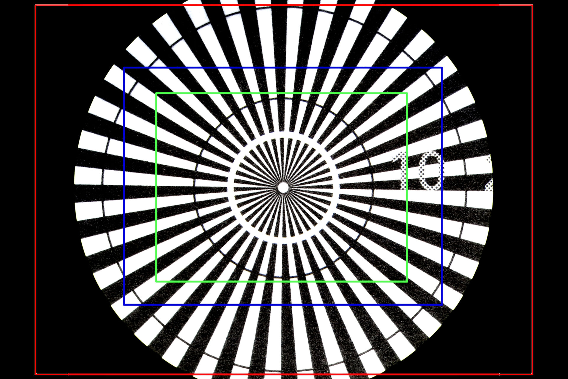
The difference in OF between images seen by the eyepieces versus those recorded by the camera sensor, for the same sample, objective, and zoom setting, are shown in Figures 3 and 4 below. For Figure 4, the total magnification of the objective and zoom lens is 1x, but several types of Leica C-mounts with different magnification have been used to install the Leica camera with a sensor size of 2/3’’ onto a M205 A stereo microscope. The red rectangle seen in Figure 4a represents the OF of Figure 4b, an image taken with the 0.32x C-mount. The blue rectangle indicates the OF of Figure 4c, taken with the 0.5x C-mount. The green rectangle shows the OF of Figure 4d, taken with the 0.63x C-mount. Figure 4b shows the problem of vignetting where the edges of the image are darker than the center. To avoid such a problem, normally it is recommended that a 0.32x C-mount is used with a digital camera having a 1/3” (8.5 mm) sensor size, a 0.4x C-mount with a 1/2.3” (11 mm) sensor size, a 0.5x C-mount with a 1/2" (12.7 mm) sensor size, and a 0.63x C-mount with a 2/3” (16.9 mm) sensor size.
 and simultaneously with the chip (rectangles) of a Leica digital camera.")
 of 1x.")
The object field (OF) of the camera sensor can be calculated using Equation 13 above. A UHD image with a 16:9 aspect ratio (3,840 x 2,160 pixels) is assumed. The range of values of the OF for the Emspira 3 digital microscope and M205 A stereo microscope equipped with a Flexacam c5 camera are shown in Table 5. Again, the magnification range for the Emspira 3 is: objective 0.32x to 5x and zoom 0.75x to 6x (the tube factor including the photographic projection lens has a 8:1 ratio from highest to smallest magnification) and for the M205 A with a Flexacam c5 camera: objective 0.5x to 2x, zoom 0.78x to 16x, and C-mount 0.4x to 1x.
Emspira 3 | OF sensor | ||
| MTOT PROJ | w (mm) | h (mm) | |
| 0.08 : 1 | 76 | 43 | max. OF |
| 9.9:1 | 0.6 | 0.3 | min. OF |
M205 A/Flexacam c5 | OF sensor | ||
| MTOT PROJ | w (mm) | h (mm) | |
| 0.16 : 1 | 38 | 21.5 | max. OF |
| 32 : 1 | 0.19 | 0.11 | min. OF |
Table 5: Object field (OF) data (Equation 13) for a UHD image (3,840 x 2,160 pixels) from the Emspira 3 digital microscope and M205 A stereo microscope equipped with a Flexacam c5 digital camera showing the range from minimum to maximum values.
Summary and conclusions
Digital microscopes use electronic image sensors (camera sensors) to replace eyepieces. Stereo microscopes have eyepieces and can be equipped with digital cameras. Digital microscopy allows rapid acquisition of high-quality images. It is often used for fast and easy documentation, quality control (QC), failure analysis, and research and development (R&D) in a variety of fields.
Due to the diversity of camera sensor dimensions and electronic display monitor sizes, determining magnification and resolution when using digital microscopy can be challenging. With this report, users of digital microscopy can better understand how to evaluate the total magnification and its useful range. In addition, helpful information concerning the object field or field of view is discussed.
Appendix
Detailed explanation for Equation 4
The basis for the definition of the total lateral display magnification, MDIS, indicated by Equation 4, is the "enlargement" of the image size displayed on the monitor in comparison to the image size projected onto the camera sensor. Thus, the ratio of the image size on the monitor to that on the sensor determines the total magnification:

For a size ratio, a single image dimension, such as the image width or height, could be used. Working with the width, then the image width on the monitor equals the number of monitor pixels in the image width times the pixel size. For the image width on the sensor, a similar argument applies, therefore:

The ratio of the monitor to sensor pixel size has been defined in Equation 5 as the pixel size ratio:

When the number of monitor and sensor pixels are the same (a 1-to-1 pixel correspondence), then:
MDIS = MTOT PROJ x Pixel size ratio
which is, of course, Equation 4 above.
However, the question arises: If 2 monitors have the same pixel size but different dimensions, will the total magnification be the same if the same image from a camera sensor is displayed on either one with a 1-to-1 pixel correspondence (i.e., no binning)?
An example (not a real case) can be used to illustrate the answer. From Table 2 there are 2 size monitors, the 21.5 inch (55 cm) FHD and 43 inch (109 cm) UHD, which have identical pixel sizes, 0.25 mm. The 43-inch monitor has 4 times as many pixels (3,840 x 2,160 pixels) as the 21.5-inch monitor (1,920 x 1,080 pixels), twice as many pixels for each dimension. Now imagine using a camera sensor also with 8.29 MP (UHD, 3,840 x 2,160 pixels) to display the same image on both monitors with a 1-to-1 pixel correspondence (signal of 1 sensor pixel, with no binning, is displayed on 1 monitor pixel). The 43-inch monitor would show the full image projected onto the sensor. However, the 21.5-inch monitor, having 4 times fewer pixels than the sensor, would show only 1/4 of the image projected onto the sensor. Still, the total magnification for the image displayed on both monitors would be the same. To prove this fact, Figure A1 below shows the same image from a camera displayed on both the 21.5- and 43-inch monitor. The white double arrow indicates the same features on the sample. The length of the arrow is the same in each image, as the pixel sizes are the same for each monitor and the feature covers the same number of pixels in each image.
 and displayed with a 1-to-1 pixel correspondence")
To further clarify the point, imagine a very large piece of paper having a rectangular hole with the dimensions of the 21.5-inch monitor. One could use the paper to cover the 43-inch monitor and an area of the image equivalent to the 21.5-inch monitor would be revealed. An example is shown in Figure A2 below. If the rectangular hole in the paper is moved around over the 43-inch monitor, then it would be similar to moving around the displayed image on the 21.5-inch monitor with software using a mouse or cursor. Again, the same features measured in the image displayed on either the 43- or 21.5-inch monitor with a 1-to-1 pixel correspondence would have the same dimensions, meaning the total magnification is the same.
 The full image displayed on the 43-inch monitor is covered with a large piece of paper having a rectangular hole with dimensions equivalent to the 21.5-inch monitor, so only 1/4 of the image is seen.")


