Introduction
Imaging with an optical microscope system is influenced by aberrations generated by the components it consists of. For example spherical aberrations, coma and axial chromatic aberrations as well as lateral chromatic aberrations and astigmatism disturb the image. Fortunately, there are measures to minimize these influences.
Classically, manufacturers tried to eliminate aberrations at the component that was generating it. Over the years philosophy changed and optics developers started to consider the microscope as a whole system. In 1992 Leica Microsystems turned this vision into a name – the DELTA system, which was a universal infinity optics system for transmitted and incident light microscopy. It allowed the unrestricted modular use of all optical contrasting techniques for all users [1].
Continuing this system philosophy, the HCS – Harmonic Component System – was the further development of the DELTA system in 1998 and is still applied. Its prominent idea is the “harmony“ between all the components of the entire microscope system. While retaining the basic aims and features, HCS made the DELTA system more versatile and opened it to allow the needs of users to be addressed and specific problems to be solved.
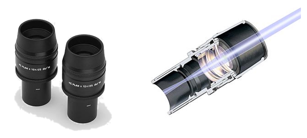
The HC system comprises these optical components, that have been matched to each other for optimal image generation and are involved in the correction of the optical aberrations:
Objectives, eyepieces, tube lenses and adapters for cameras.
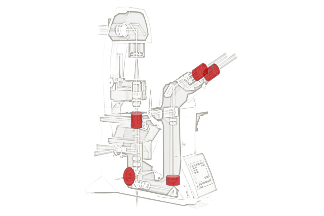
Its implementation in the 1990s still influences recent microscopes since the marked modularity of modern research microscopes highly depends on the harmonization of all optical constituents (Fig. 1).
Harmony of optical and mechanical fitting dimensions
In the course of the development of infinity optics, profound technical experience was gathered with “long“ (reference focal length 250 mm of the metallurgic microscopes until 1987) and “short“ (160 mm tubelength) reference focal lengths and their advantages and disadvantages were critically analysed. With the introduction of the DELTA concept in 1992, the reference focal length 200 mm was defined as the new Leica standard for the optimum length for the efficient design of the whole system. This concept harmoniously united the advantages of former systems, while eliminating their system disadvantage [1].
The classic RMS (Royal Microscopical Society) objective thread was adopted as the standard thread in microscopy by the Microscopical Society of London in 1858. Developments in infinity optics and changes in user requirements, e.g. a growing demand for highaperture objectives in fluorescence microscopy, made it evident that the RMS thread would inhibit further progress. To create new degrees of freedom, Leica introduced the new M 25x0.75 objective thread with the DELTA system in 1992.
During development of the DELTA system, the necessity and possible advantages of a new, larger parfocalising distance of the objectives was also examined.
The parfocalising distance d is a purely mechanical dimension, i.e. the distance between the object plane and objective shoulder (Fig. 2a). When the objective is changed by turning the nosepiece, the image focus is more or less retained (parfocality). Besides determining the amount of space for integrating lens elements, the parfocalising distance also influences the structural and ergonomic design of the objectives and the entire microscope system.
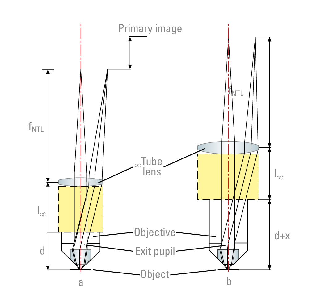
Although a long parfocalising distance, such as 60 mm or more, offers certain advantages for designing objectives in the threshold range between microscopy and macroscopy, it has considerable disadvantages for a technically and applicationally well-balanced design of the microscope range as a whole.
Apart from increasing the size of the objectives and following optic modules, which would incur the disapproval of many users, a longer parfocalising distance also has an adverse effect on ergonomics. The viewing port of upright microscopes and the specimen stage position of inverted microscopes are inevitably raised in proportion to the increase in parfocalising distance.
The position of the rear focal plane (exit pupil) of the objectives plays an important role in the correction of the following tube lens and also in the optical and geometric design of the image contrast modules situated in the infinite light path between the objective and the tube lens. The longer the parfocalising distance, the longer the distance between the exit pupil and the following optical elements, causing larger diameters, correction problems, higher costs, etc. A longer objective parfocalising distance increases the centration sensitivity of the objectives in general [2], which is particularly disadvantageous for high performance objectives (Fig. 2 b).
After careful analysis and consideration of all key aspects for a homogeneous microscope range, Leica decided to stay with the parfocalising distance of 45 mm, which had already proved the optimal solution in the DELTA optics. The continued use of these fitting dimensions for the HCS system guarantees a harmonious answer to the optical, mechanical and ergonomical demands of the entire “microscope workplace“.
Harmony in Imaging
The described mechanical and optical fitting dimensions define the geometric framework for the composition of the optical components used for imaging and correction of optical aberrations.
Every single component involved – objectives, eyepieces, tube lenses, camera adapters, etc. – has a different physical job to do and therefore has its own specific requirements of the correction of the physically inevitable optical aberrations. The cause and effect of the aberrations requiring correction have already been described in detail [1].
Various approaches have been taken in microscopy for the optical design of the “entire microscope system“ and the distribution of the correction work among the components involved.
At first, the approach of designing each component to be aberration-free in itself seems attractive. Although this is possible in principle, it carries the risk of correction “overload“: the cost is too high and limits of what is possible are reached or overstepped.
It has proved far better to view the correction of certain optical aberrations holistically for the whole microscope system and to distribute the effects among several system components.
Spherical aberrations, coma and axial chromatic aberrations are effectively corrected at source, i.e. in the component where they originate. However, it was discovered very early on that lateral chromatic aberrations and astigmatism are best corrected by delegating correction work to the objectives and eyepieces [3]. Since the introduction of infinity optics, every microscope has a tube lens system, required for the formation of the real intermediate image. As we have already described, this system can be used to establish a specific state of correction in the intermediate image [4], creating additional degrees of freedom.
With the launch of DELTA optics in 1992, the compensation of lateral chromatic aberrations of the objectives was transferred from the eyepieces to the infinity tube lens. This was another important step on the way to the HCS system, bringing particular advantages for designing widefield eyepieces.
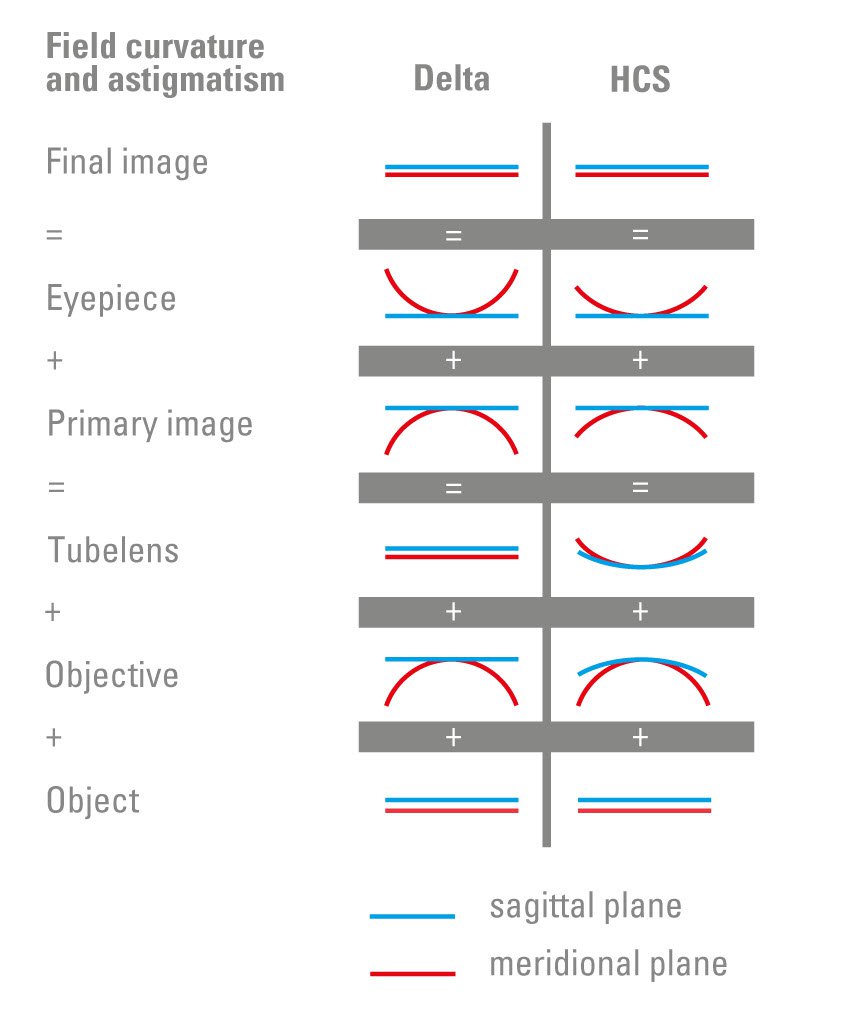
In optical imaging, astigmatism is the name given to the typical phenomenon that off-axis specimen details extended in a radial or tangential direction are focused at different distance, i.e. on the convex sagittal or meridional image surface. When astigmatism is eliminated, these coincide to form a single – in simple cases also convex – image surface (field curvature). In an ideal optical system without field curvature and astigmatism image surfaces lie in the Gaussian image plane and the specimen details are sharply focused in the entire field of view.
The residual field curvature after the correction of astigmatism mainly depends on the type of objective used. The more complex the construction of the objective, the smaller the field curvature. The extent of astigmatism is particularly influenced by the shape of the lenses. Simple types of objectives such as achromats always have a certain remaining amount of astigmatism when the basic requirement of aplanatic correction, i.e. correction of spherical aberrations and coma, has been met. With simple aplanatically corrected eyepieces, it has been possible to compensate this residual astigmatism with adequate success in a “natural“ way.
Additional correction of the remaining field curvature only became possible with the development of the more complex plan objectives, although eyepieces were not involved in this. However, experience has shown that it is more beneficial to distribute curvature and astigmatism correction work more evenly among the components involved, including the tube lens. This has happened with the HCS system (Fig.3).
In concrete terms, this means that part of the objective’s contribution to the correction of field curvature is taken over by the shared compensation workload of the following components. This makes the objectives “more relaxed“ and creates more degrees of freedom for special applications.
Harmony of technology and application
Not only can the microscope components among themselves be harmonized but also their combination with the relevant application. Especially objectives can be customized according their tasks. Mainly because of fluorescence applications, high UVA transmission with low autofluorescence is necessary besides excellent field flattening and chromatic correction.
Contrast, field flattening
A generally accepted criterion for the quality of objectives is the Strehl intensity ratio, which gives the relation of the intensity in the centre of the diffraction disk for an image formed with an aberrated objective to the corresponding intensity with an otherwise identical, but ideally corrected objective [5]. The size of this value is decisive for image contrast. In optical design, a Strehl intensity ratio of 99% in the centre of the image is aimed at and also achieved. To meet highest requirements manufacturing tolerances must not cause this value to fall under 95% for high performance objectives. Literature on the subject allows a Strehl intensity fall-off to 80% at the edge of the image field in accordance with the physiological properties of the human eye.
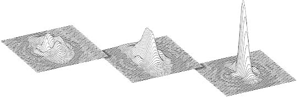
The point-spread function (PSF) is used for the visual 3D display of the intensity distribution in the Airy diffraction pattern of a self-luminous point. The height (intensity) and width of the central maximum depend on aperture. While Strehl intensity describes the performance of the objective with only one number, PSF gives information on the extent and nature of the residual error. Spherical aberration, coma and astigmatism can therefore be easily differentiated.
The higher and thinner this pattern is, the higher the contrast and resolution. If there are aberrations, the intensity drops in the central maximum and rises in the diffraction rings, which leads to reduced contrast. Apart from this, the rotation symmetry and therefore imaging accuracy diminishes towards the edge of the image.
Fig. 4 shows the performance improvements made by the HCS system taking the typical example of the 40x objective.
Working distances to suit the application
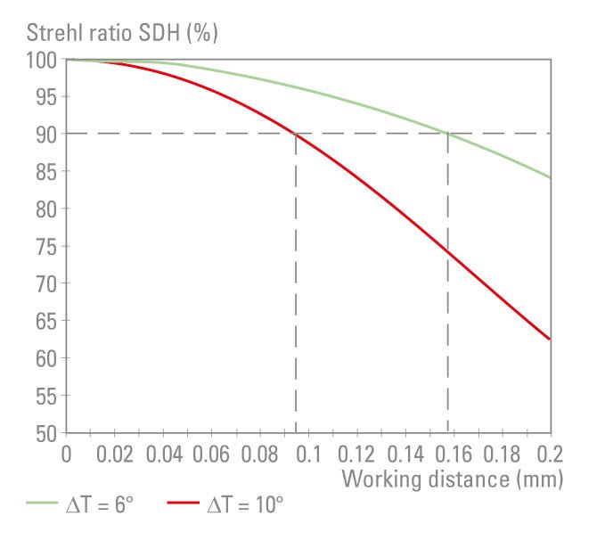
Occasionally, a longer free working distance is highlighted as a special performance feature of high aperture oil immersion objectives. However, a supposed advantage frequently turns out to be a disadvantage in practice.
Oil immersion objectives with a very high aperture reach their full optical performance only in a relatively narrow temperature interval because of the abrupt change in the refractive index of the immersion oil as a function of the temperature. As can be seen from Fig. 5, the thicker the oil layer, the more the temperature-specific change in the refractive index impairs the image. For reliable application, the free working distance therefore has to be matched to the temperature intervals that commonly occur in practice, i.e. free working distance of much more than 0.1 mm are not suitable.
CORR-objectives to suit the application
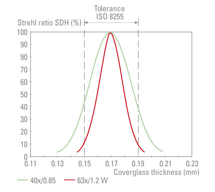
Some objectives in the HCS system have been given a correction mount to be able to realize the optical performance potential of the objective, even for special applications with changing optical conditions in the specimen. When designing the objectives, certain assumptions on the thickness and refractive index of the coverglass and immersion media are accounted for in the correction.
If conditions differ from these assumptions, spherical aberrations occur, causing contrast to suffer. This fault can be remedied by calculated changes to the spacing of lens groups. The following can be corrected:
- deviations of the coverglass thickness from the nominal value (Fig. 6)
- different immersion media
- temperature deviations of the immersion media
- refractive index influences of the specimen when focusing below the surface
Objectives for electrophysiology
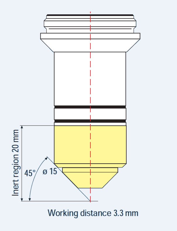
In electrophysiology, cells are handled with micromanipulators in temperature controlled aqueous solutions. The slightest currents and voltages of nerve cells, for example, are measured at a constant temperature. This makes specific demands of the mechanical properties of the objectives (Fig. 7), such as
- slender mount with as large an access angle as possible
- inert, scratch-resistant surface for the whole of the front part
- minimal surface conductivity
- minimum thermal conductivity
The optical design also has to fulfil special requirements:
- long free working distance
- wide-band APO correction of 400 – 1000 nm
- DIC in the NIR range due to stray light effects in thick specimens
- high UV-A transmission for fluorescence
- minimum autofluorescence
- suitability for confocal microscopy
A series of objectives had been specially designed to meet the specific needs of this field of application. Here, too, the HCS system made it possible to reconcile contradictory extremes in terms of optical performance requirements.
HC eyepieces
We already talked about lateral chromatic aberration in [1]. In the eyepieces, it does not increase linearly towards the edge of the image field as it does with objectives (“zone behavior“). A similar non-linear behavior is also shown by the meridional and sagittal image curves of the previously used types of eyepiece. In contrast, the corresponding field curvatures of the objectives are “zone-free“. This contradictory behavior is difficult to harmonize, i.e. a certain amount of astigmatism remained despite skillful reconciliation with large image fields. In the HCS system the eyepieces have taken over a larger proportion of curvature correction from the objectives. This task led to more complex eyepiece types with greater degrees of freedom for correction of remaining aberrations such as distortion and astigmatism. As a result, the HC eyepieces offer “zone-free“ correction of the field curves.
Summary
Over the years of microscopy development it turned out that it is worth seeing the microscope as a system. With the introduction of the HC system in 1998, Leica Microsystems further developed this vision which is still valid today. Its technical concept is based on the optical and mechanical fitting dimensions for parfocalising distance, objective thread and reference focal length introduced with the DELTA system in 1992.
The HC system constitutes a harmonization of the optical correction effect among the system components involved. This made it possible to retain the universal application potential of the optic system while designing objectives which additionally address specific application requirements e.g. fluorescence and confocal microscopy or electrophysiology.
References
[1] Schade, K.-H., Euteneuer, P. a. Müller-Rentz, A.: Delta – The new System of Microscope Optics from Leica, Scientific and Technical Information, Vol. X, No. 4, pp. 114–122, 1992.
[2] Haferkorn, H.: Optik, Verl. Johann Ambrosius Barth, Leipzig, 1994.
[3] Metz, C.: Neue Okulare zur Ebnung der Gesichtsfelder der Apochromate, Z. f. wiss. Mikr. u. f. mikr. Techn. 37, S. 49–52, 1920.
[4] Schade, K.-H. u. Klein, W.: Optical System for Tube Length Infinity – What Are It’s Advantage?; Scientific and Technical Information, Vol. VI, No 5, pp. 185–191, 1975.
[5] Beyer, H.: Handbuch der Mikroskopie, VEB Verlag Technik Berlin, 1973, S. 91.
[6] ISO 8255/1 – 1986: Optics and optical instruments – Microscopes – Cover classes – Part 1: Dimensional tolerances, thickness, and optical properties, First edition – 1986-09-01.
[7] Hell, S., Reiner, G., Cremer C., Stelzer, E. H. K.: Aberrations in confocal fluorescence microscopy induced by mismatches in refractive index, J. Microsc., Vol. 169, S. 391–405, 1991.
[8] Krüger, R.: Contrasting techniques of the new Leica DM R HCS microscope system, Scientific and Technical Information, Inf. CDR 1, pp. 37–46, August 1988.
[9] Schönenborn, J.: The illumination optics in the new Leica DM R HCS microscope, Scientific and Technical Information, Inf. CDR 1, pp. 25–36, August 1988.
[10] Schade, K.-H.: Light microscopy: Technology and Application, Landsberg/Lech; Verl. Moderne Industrie, 1993.