Introduction
For image acquisition, the specimen preparation has two major requirements. The specimen needs to be placed into the focal plane of the detection objective in between the two mirrors of the cap. In addition, it needs to be slightly elevated from the petri dish bottom for the mirrors/light sheet to reach the specimen’s distal part.
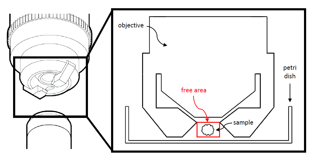
One convenient way to position specimens in the free area of the sample space (see figure above) is by using FEP (fluorinated ethylene propylene) tubes (see figure below). With a refractive index, n, of 1.338, FEP is well suited for imaging specimens immersed in aqueous solutions (at least when using objectives with moderate numerical apertures [NAs]).
 tubes.")
For SP8 DLS imaging, specimens can be positioned and fixed in place using an FEP tube (see diagram below).
The advantages of this kind of specimen mounting are:
- easy handling and
- possibility to use low concentration of scaffolding medium (e.g., agarose or methylcellulose) which provides enough specimen confinement under physiological conditions for long-term in vivo imaging.
The disadvantage is the difficulty to align the specimens such that the region of interest is exposed to the side used for fluorescence detection.
To overcome this disadvantage, while maintaining the aforementioned advantages, a rotation device has been designed which allows the angle of the FEP tube to be easily adjusted, so that the specimen can be optimally aligned for imaging. Such set-ups have previously been demonstrated elsewhere [1, 2, 3].
Materials and methods
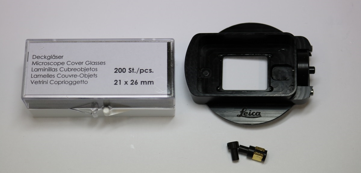
The sample rotation device (see above, 158007064) for DLS imaging comes with:
- the DLS rotation device;
- microscope glass cover slips (21 x 26 mm); and
- FEP tubes (Camitec, outer diameter 2.00 mm, inner diameter 1.80 mm).
However, there is no silicone or other material for sealing the cover slip included with the rotation device.
Step 1: Cleaning of FEP tubes (recommended procedure)
As described in the report by Kaufmann et al. [4], FEP tubes should be treated in the following way before usage:
- first, all solutions must be degassed and syringe filtered (Millex-HV, PVDF, 0.45 µm);
- rinse with 1 M NaOH (Merck);
- place them in 0.5 M NaOH and ultrasonicate for 10 minutes;
- rinse with double-distilled H2O and 70% ethanol
- ultrasonicate in 70% ethanol for 10 minutes;
- rinse with double-distilled H2O; and
- finally, store in double-distilled H2O.
Step 2: Sealing the rotation device with the glass cover slip
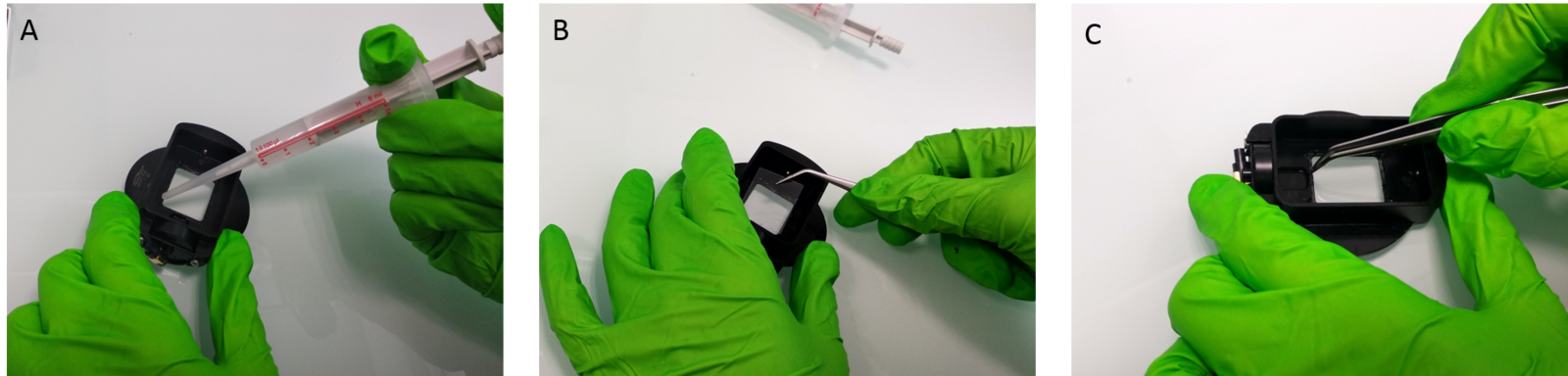
Sealing of the cover slip onto the rotation device is done in the following manner:
- apply silicone to the inner edge of the recess at the bottom of the rotation device (see A below);
- add a cover glass and press the glass lightly to ensure that it sits evenly for a good seal at all points (see B below); and
- to check the chamber seal, add some distilled water to the rotation device and see if leaks occur (see C below).
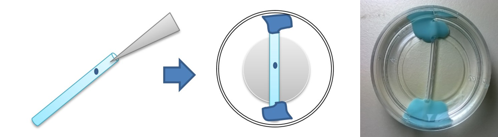
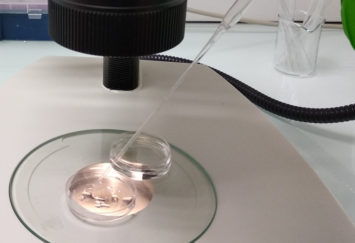
Step 3: Placing the specimen(s) into the FEP tube
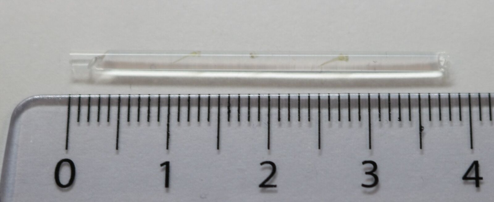
Specimens are placed in the mounting medium and drawn into the tube with a pipette or syringe (shown below).
The FEP tubes need to have a length of 38 mm.
Step 4: Inserting the FEP tube into the rotation device
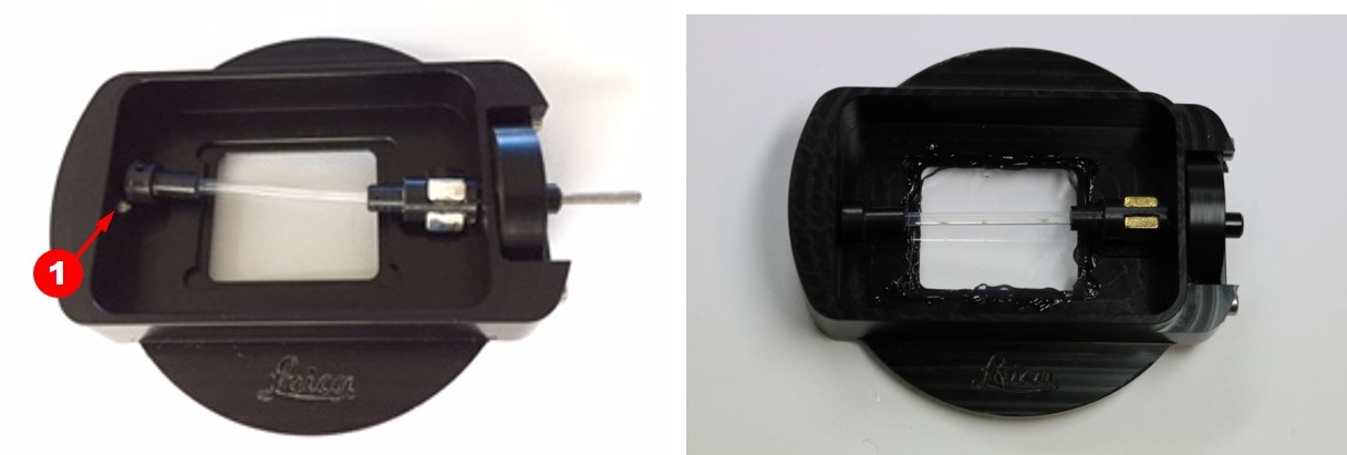
Attach the black caps on both sides of the FEP tube (see A and B below).
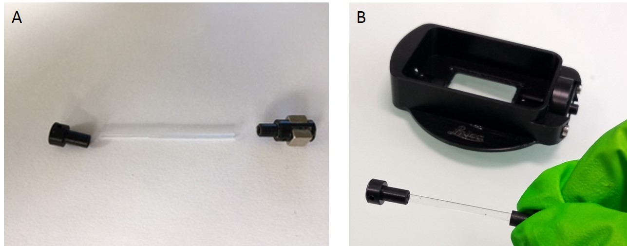
As seen below, insert into the rotation device’s pin (1), the end of the FEP tube with both a black cap and magnet (2).
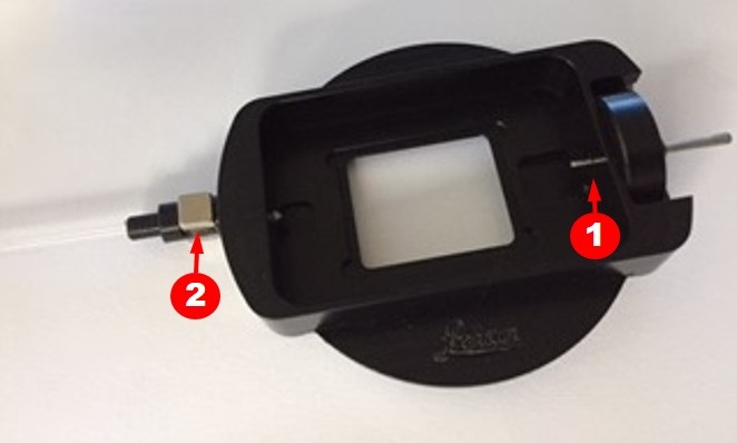
Finally, the opposite side of the tube is fixed in place (1 in image below).
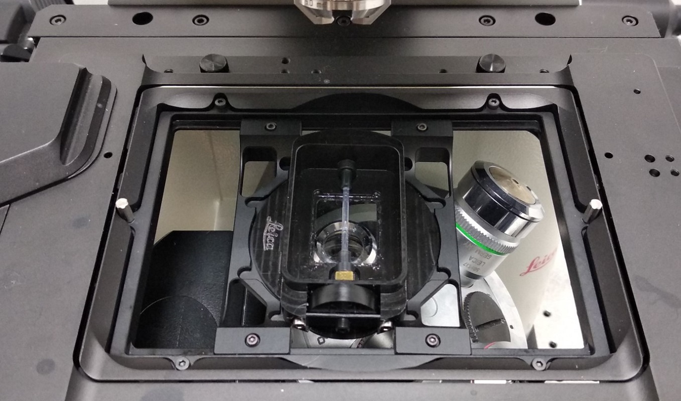
Step 3: Start Image Acquisition
Position the glass bottom petri dish on top of the TCS SP8 DLS scanning stage (see below).
Note: The rotation device is only compatible with the following z-Galvo stage inserts:
- 158004118 Rotatable Insert Inverse and
- 158004119 Insert Universal.
Be careful: Only put the rotation device onto the z-Galvo stage after initialization. Also, pay attention when changing (illumination) objectives. The wheel for the rotation device protrudes downwards and might touch accidentally an objective (it may be best first to remove bulky objectives from the turret).
Results
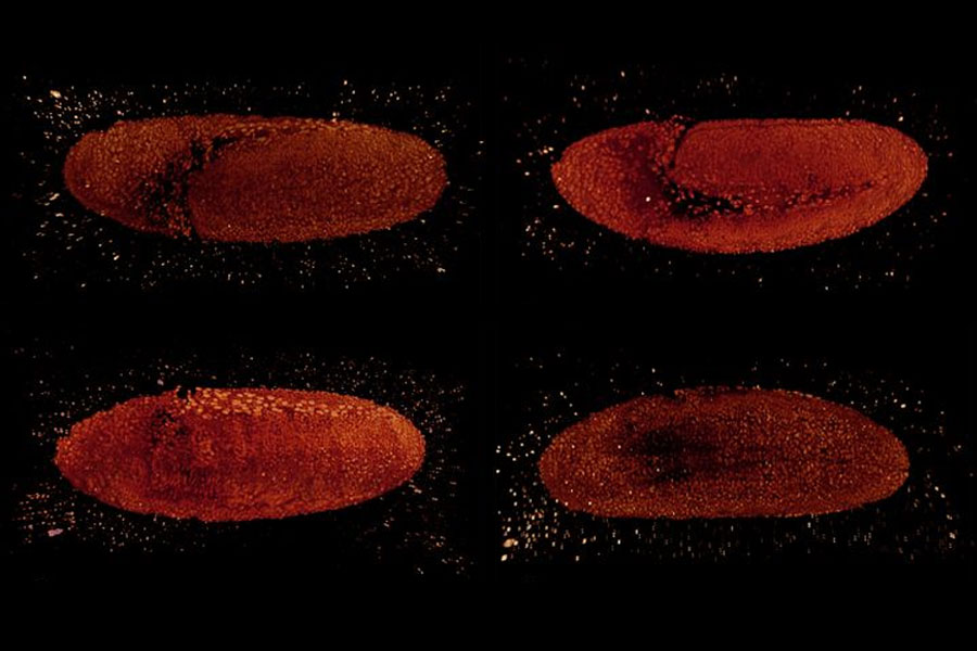
Using the LightSheet Wizard, which is included with the LAS X software, you can now acquire images of your specimen(s).
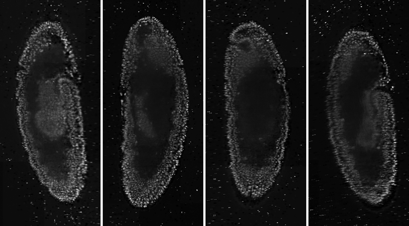
Figure 12: Drosophila embryo observed from different sides. Single planes were taken from 3D image stacks. Courtesy of Pavel Tomancak, MPI-CBG, Dresden, Germany.

.")

