
Introduction
Electron microscopes such as transmission and scanning electron microscopes (TEM and SEM respectively) are widely used to obtain structural insight into biological samples or inanimate materials. For the EM (Electron Microscopy) applications thicker specimens are sliced into ultrathin sections with a thickness of less than 100 nm.
This allows for acquisition of high-resolution EM images and, as a next step, computational reconstruction of information gathered from multiple subsequent sections, providing an overview of a thicker sample (Volume EM).
Trimming of the sample block
To create uniform sections of a defined thickness, multiple manual steps have to be performed with the appropriate skills and expertise to meet the necessary preconditions.
Coarse trimming
Before the actual volume of interest can be sliced, the sample has to be initially trimmed to reveal the specimen and to remove excessive sample-free polymer or non-targeted sample areas. Usually the trimming results in a (stacked) pyramidal shape with decreasing size (Figure 1).

First, coarse trimming is done either manually with a razor blade or by using the EM RAPID to create the pyramid frustum. This specimen trimming device´s high speed diamond milling head can be oriented towards the sample at a specific angle while the sample is turned 90 ° in four rounds (Figure 2).

Fine trimming
Next, the sample block is mounted into the ultramicrotome, and the sample area is reduced and shaped using a trimming knife to create the final block face. The aim is to contain the sample in a small rectangular or trapezoidal area of less than 1 mm2 and to get the upper and lower edge perfectly parallel to the knife (Figure 3). This will in later steps allow the sections to adhere to each other forming ribbons. The ribbons are collected whole and enable the user to follow the order of sections, which is especially useful for array tomography applications.

The alignment between sample and knife
After the sample block is trimmed to obtain a flat and exposed block face, it is crucial to correctly align it to the knife edge. The final goal is to keep the distance between sample and cutting plane as small as possible to avoid loss of material and incomplete sample sections.
Perfect alignment is a challenging task. It requires subtle manual manipulation of the sample tilt, rotation, and knife angle adjustments, as well as the correct sample advance (feed).
This is particularly difficult for new or infrequent ultramicrotome users. Not only is there a high risk of damaging the expensive knife, but also of making the sample unusable for sectioning. Nevertheless, even experienced operators need to be careful to ensure they do not lose too much material in a thin sample (such as a cellular monolayer) due to an initial misalignment.
The method
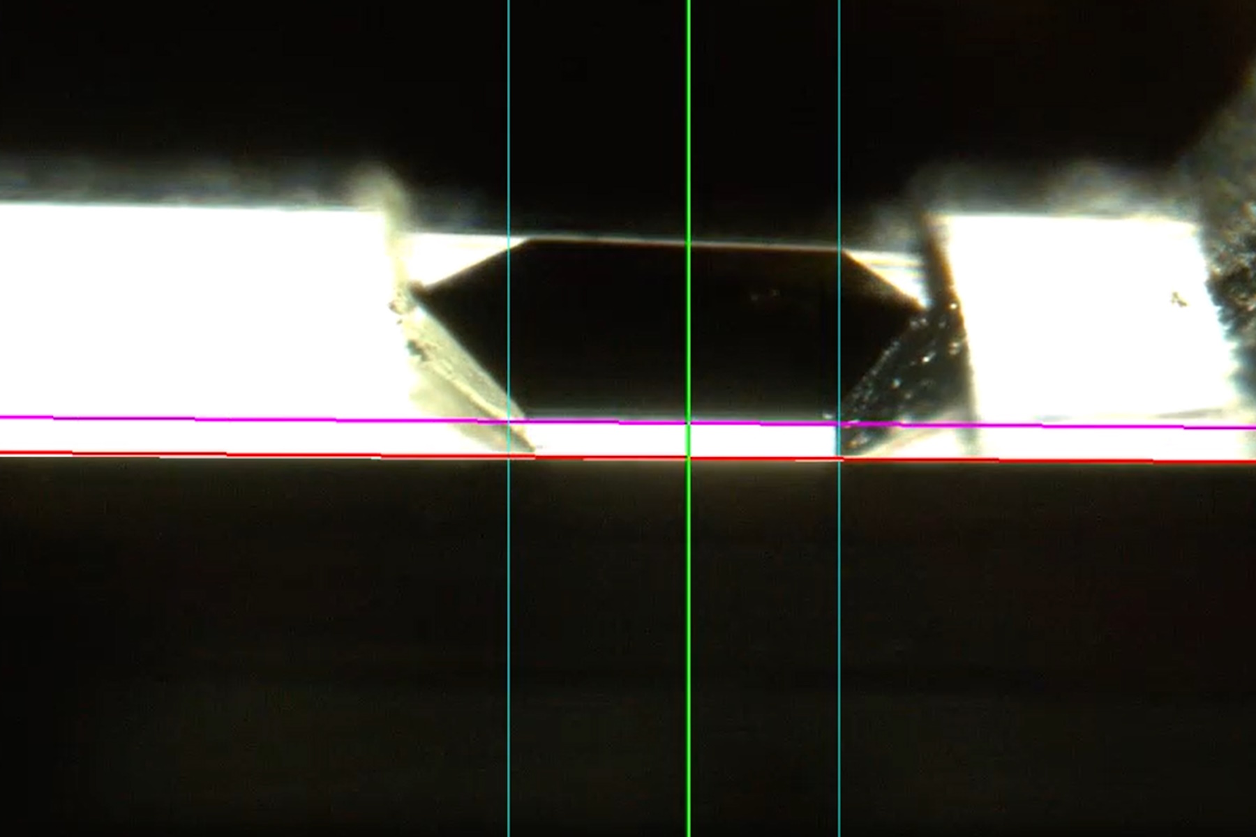
To judge the distance between knife and sample the users need to visualize the gap between them using backlight illumination. The observation is performed under the stereo microscope. The back of the knife is illuminated from below and reflected by the smooth surface of the block face towards the user appearing as a bright stripe (Figure 4). This is referred to as the “light gap”.
Perfect alignment demonstrates itself as a thin (blue colored) light gap of uniform thickness throughout the entire length of the block face (see below).

The following steps are commonly performed in an iterative order until the approach and alignment is achieved. Typically, a distance of less than 500 nm between the block face and the cutting plane can be reached.
The sample rotation
To ensure the sections can adhere to each other and create a ribbon, the upper and lower edge of the sections have to be perfectly parallel. This can only be achieved if the block face meets the knife over its entire length. Hence, the sample must be rotated to be parallel to the knife edge (Figure 5).

As a first step, the knife block is shifted close enough to the sample to create the light gap. As soon as the light gap is visible in the block face, the user needs to adjust the sample rotation such that the leading lower edge is parallel to the knife. It might be impossible to parallelize the sample and the knife without adjusting the knife angle, as the block face might not have been trimmed perpendicularly.
The knife angle
To compensate for the angle between the block face surface and the knife, the knife needs to be rotated until the leading edge of the block face is parallel to the blade. (Figure 6). This will ensure that the sample meets the knife over the entire length from left to right, providing full sections without losing too much material until full sections are reached. Furthermore, it ensures a homogenous cut and allows the sections to adhere to each other, forming ribbons in the boat of the knife (Figure 6, lower image).

The sample tilt
One of the most critical, but unfortunately less obvious orientations is the sample tilt. If the sample tilt is not correct, the knife blade will not be in line with the sample movement during cutting. As a result, the sample's precious portions could be lost before a full section of the block face is created.
The sample tilt is changed by moving the sample along the segment arc adjusting the angle between the block face and the knife edge. Using the light gap as an indicator, the user needs to move the sample up and down during adjustment until the light gap shows the same height over the entire block face (Figure 7).
This is done in an iterative approach by adjusting the sample tilt. At this stage one needs to be careful not to move the knife too close to the sample, otherwise the closer part of the block face can be cut off entirely, risking loss of the whole sample. At the same time there is a risk of the knife becoming damaged.

Using the light gap as indicator for all adjustments
The final step for each of the sample and knife angles is the adjustment using the light gap as an indicator. After the adjustment of the segment arc, the knife is advanced carefully towards the sample until the light gap between knife and block face is barely visible. During the approach, the color of the light passing through the gap will change until it is finally blueish (change of the color is a result of diffraction, Figure 8). Using this method, an alignment with a deviation of less than 1 µm is possible over the entire block face. A blue light gap, where blue light is reflected from the block face typically indicates a distance of approximately 400 nm between the block face and the knife. An evenly distributed light gap across all angles at this distance is the most precise indicator of a correct light gap setting, which ensures minimal loss of material.

The solution
Upon reviewing the detailed steps required to align the sample with the knife, it is evident that the process is complex, with numerous stages and potential points of failure, that could result in significant waste of time and resources. This is especially applicable to those who are new or do not so often use an ultramicrotome.
To address these potential difficulties, it would be advantageous to automate the most critical aspects of the alignment procedure. UC Enuity, the next generation ultramicrotome from Leica Microsystems, provides precisely this solution.
The components
UC Enuity offers a new automated module, which brings block face and knife together using motorized components. This allows a very precise manual alignment, but also a completely automatic adjustment of the ultramicrotome (Figure 9).
 and knife block (2)")
The built-in digital flexacam (i5 or c5) provides images of the knife and light gap, which are analyzed, and the information is sent back to facilitate automatic alignment (Figure 10).

The alignment process guides the user through the approach phase where the final alignment step is performed automatically. This automation was developed to protect the knife and the block face from damage while also helping the user to achieve perfect alignment. This enables untrained users such as those working within a core facility or research group to obtain high quality sections quality without the risk of damage during the initial orientation phase of knife and sample.
It should be noted that for a fully automatic sequence to be carried out, certain preconditions have to be met. For example, the block face size must be a minimum of 250 x 250 µm and a maximum of 1200 x 1200 µm. In addition, the block face must be reflective and sufficiently clean.
The automated workflow
To start the autoalignment procedure the knife should first be approached to the block face and centered. After confirmation by the user the automatic alignment will be performed (Figure 11).

The software detects the different edges within the image and performs an iterative alignment of the knife angle, the sample tilt, and the sample rotation. During the procedure, the sample is rocked up and down to visualize the light gap over the complete height of the block face and to adjust the sample tilt accordingly.
At the end of the process one can approach the knife to the sample automatically up to an approximate distance of 5 µm (Figure 12). A manual correction can be carried out as well, if necessary.

Representative data of several approaches
The aim of the alignment process is to avoid the sample being removed unnecessarily until a full section is achieved. To offer definitive proof that the automatic alignment method reliably produces high quality section, samples were tested against a panel of ultramicrotomy experts.
In the first group of representative samples, the alignment was carried out manually by the experts. Typically, the experts needed to cut 5-10 partial sections with a thickness of 100 nm until a full section was achieved (Table 1). Another group of samples were trimmed using the automatic alignment function of the UC Enuity, with five different samples trimmed with different devices, resulting in different block face sizes. In both groups of tests, the number of partial sections on average was below or equal to 10, while minimal numbers of partial sections were between 3 and 7 (Table 2). This proves that alignment can be successfully achieved with UC Enuity autoalignment.
Expert | Sample type | Trimming | Block face width approx. | Number of 100 nm sections until full section |
#1 | Epon, cylindrical mold | Diamond knife | 300 | 5 |
#2 | Epon, cylindrical mold | Diamond knife | 500 | 10 |
#3 | Epon, cylindrical mold | Diamond knife | 200 | 7 |
#4 | Epon, cylindrical mold | Diamond knife | 300 | 6 |
Table 1: Number of partial sections until full section achieved by ultramicrotomy experts.
| Sample type | Trimming | Block face width [µm x µm] | Average number of 100 nm sections until full section (minimal number) |
1 | Epon, cylindrical embedding mold, | 90 ° diamond knife | 500 | 8 (min. 5) |
2 | Epon, cylindrical embedding mold, | 90 ° diamond knife | 1000 | 8 (min. 6) |
3 | Epon, cylindrical embedding mold, | 45 ° diamond knife | 250 | 8 (min. 3) |
4 | Epon, cylindrical embedding mold, | 45 ° diamond knife | 500 | 10 (min. 7) |
5 | Epon, cylindrical embedding mold, | 45 ° on EM RAPID with diamond milling tool | 1000 | 10 (min. 3) |
Table 2: Number of partial sections until full sections are achieved after automatic alignment by the UC Enuity.
Test 1, n=4; test 2, n=2; test 3, n=4; test 4, n=7; test 5, n=2.
Summary
In ultramicrotomy, it is vital for knife and sample to be aligned to achieve high sectioning quality and to reduce loss of sample material until full sections are achieved.
As the alignment procedure is sophisticated and requires user experience when performed manually, the automatic alignment solution provided by the UC Enuity helps inexperienced and infrequent users to reduce the risk of damage to their sample or knife. UC Enuity also helps them to achieve a perfect light gap setting, providing the basis for good sectioning quality.
, insulin SGs (orange), microtubules (red), nucleus (yellow), and plasma membrane (transparent).")

-b-poly(isoprene). Right: Poly(styrene)-b-poly(methyl methacrylate).")
