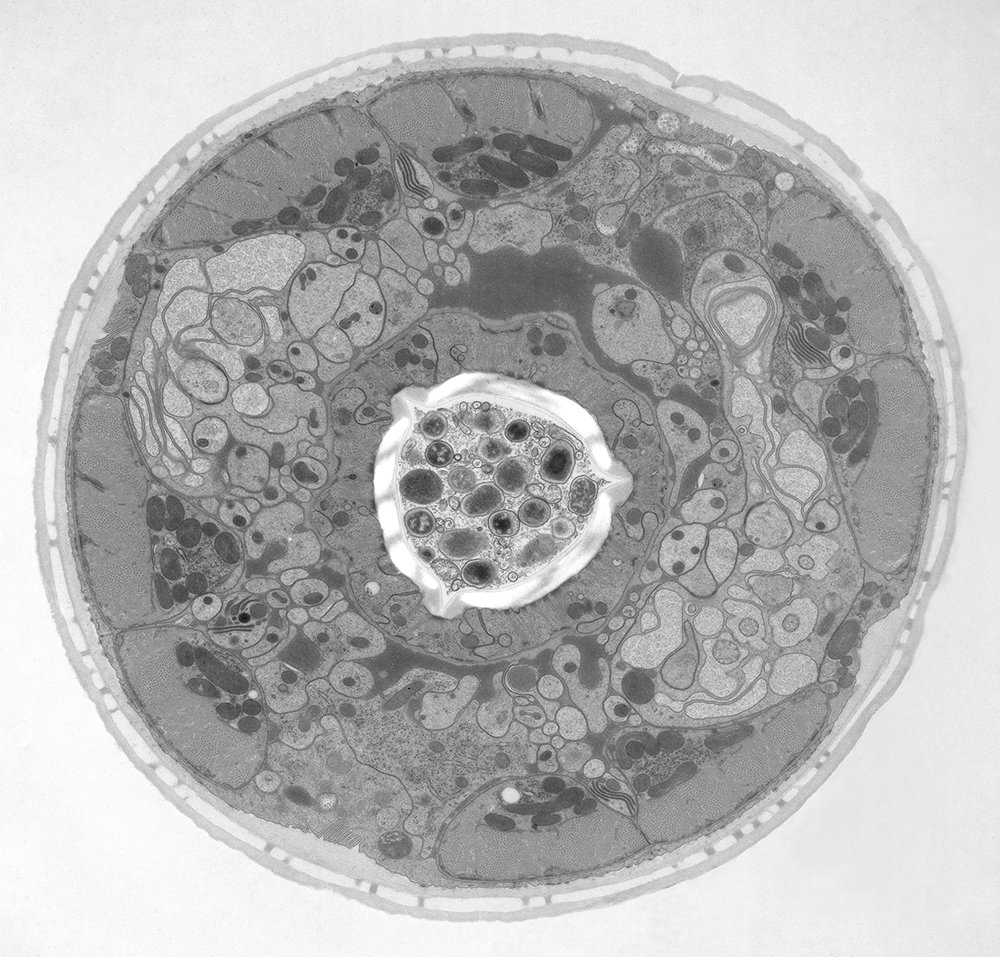
 image of a cross section of C. elegans (roundworm). Courtesy of T. Müller-Reichert, MPI-CBG, Dresden, Germany and K. McDonald, University of California, Berkeley, USA.")
What is cryo-fixation?
Water is the most abundant constituent in cells and, therefore, important for preserving cellular structure. When preparing biological specimens for electron microscopy (EM), a common way used to stabilize cellular constituents without introducing significant structural alterations is cryogenic fixation. Cryo-fixation has two distinct advantages [1]. It is achieved within several milliseconds and ensures simultaneous immobilization of all macromolecular components in cells. Many protein networks are very unstable and can fall apart with the slightest osmotic or temperature change. These unwanted effects are minimized with cryo-fixation. Fixation enables improved ultrastructural preservation of biological specimens for EM and can help facilitate even the study of dynamic cellular processes.
There are two common methods employed for cryo-fixation: plunge freezing and high-pressure freezing. The only method capable of vitrifying thicker specimens up to 200 µm is high-pressure freezing.
Successful cryogenic fixation, also known as vitrification, is the transformation of water from a liquid to an amorphous solid state without inducing the nucleation of ice crystals. Under normal conditions, when water freezes and becomes ice, it forms a crystalline structure. However, the nucleation of ice crystals depends on the temperature and pressure (see figure 1 below). Crystallization also depends on the cooling rate, as freezing is a time-dependent process. The cooling rate of a specimen with water depends on the thermal properties of water, the specimen thickness, and the heat extraction flowrate at its surface.
 depending on pressure and temperature.")
As shown in the diagram above (figure 1), whether water is in a liquid or solid (ice) phase depends on the pressure and temperature [2]. At a pressure of 2,045 bar, the melting point of water is lowered to 251 K and the temperature for homogenous nucleation is reduced to 181 K. Note that the water freezing point at 1.013 bar or 1 atmosphere is 273 K or 0°C.
What is high-pressure freezing (HPF)?
The idea of freezing biological specimens under high pressure was first introduced in 1968 [3-5]. HPF devices became commercially available in 1985. All of the currently available ones, despite having different designs, deliver synchronized pressurization and cooling of specimens within 20 ms in a highly reproducible manner. An example of a biological specimen which was prepared with high-pressure freezing and imaged with electron microscopy (EM) is shown below in figure 2.

Electron microscopy (EM) of HPF cryo-fixed specimens
More examples of biological specimens prepared with HPF (high-pressure freezing) and analyzed with EM are shown below in figure 3, 4, and 5.
 prepared with HPF. Courtesy of Dr. Syed and Dr. Bleck, NIH, USA.")
Fig. 3: EM micrograph showing an overview of a gastric caeca from Drosophila (fruit fly) [6] prepared with HPF. Courtesy of Dr. Syed and Dr. Bleck, NIH, USA.

Fig. 4: A dinoflagellate-plankton specimen prepared with HPF and imaged with EM [7]. The scale bar is 5 μm.

Fig. 5: EM image of a specimen of an Arabidopsis leaf, infected with a parasitic Albugo oomycete, a fungus-like microorganism [8]. The image was taken after HPF preparation. Additionally, actin in the leaf is expressing green fluorescent protein (GFP). Courtesy of K. Findlay, John Innes Centre, Norwich, UK.
Cryo-electron microscopy of vitreous sections (CEMOVIS)
CEMOVIS is a method of specimen preparation for electron microscopy (EM) imaging [9]. A biological specimen is cut into thin sections and then cooled extremely fast to maintain a hydrated vitreous state. The prepared specimen is observed with EM at low temperature.
Sections of yeast were prepared with a Leica high-pressure freezer. The cell paste was mixed with a pH 6.5 MES/dextran buffer so that a final MES concentration of 50 mM and a dextran concentration of 20% was achieved.
The specimens were sectioned on a Leica ultramicrotome with the micromanipulator at -140 °C and the section thickness was set to 50 nm. The sections were attached to Agar lacey grids.
The sections were imaged using a Tecnai Polara 300KeV (FEI, The Netherlands) EM equipped with a 4 K Gatan CCD camera. The magnification for the sections was 23,000x with a defocus of -6 µm for the tomogram and -8 µm for the projection image. The diffraction was done with a camera length of 930 mm. The image in the left part of the panel is an average of the central 10 slices of a reconstruction done with the IMOD package [10] image processing software from a tomogram collected using the FEI software.

Fig. 6: Images of a yeast specimen prepared with HPF and ultramicrotomy: Left) optical slice from a tomographic reconstruction; Top right) EM micrograph showing a yeast cell; and Bottom right) diffraction pattern image. Courtesy of J. O'Driscoll, D.K. Clare, and H. Saibil, Department of Crystallography, Birkbeck, University of London, UK.
. Courtesy of Al-Amaudi A, DZNE, Bonn, Germany.")
Advanced HPF with light and electrical stimulation can be achieved using the EM ICE platform. It is an optimal platform for preparing biological specimens to be analyzed with EM, as it keeps the specimens in their native state and enables the study of dynamic events.
 embedded in bulk vitreous ice (blue).")

, insulin SGs (orange), microtubules (red), nucleus (yellow), and plasma membrane (transparent).")
