
The problem: Why are images blurry?
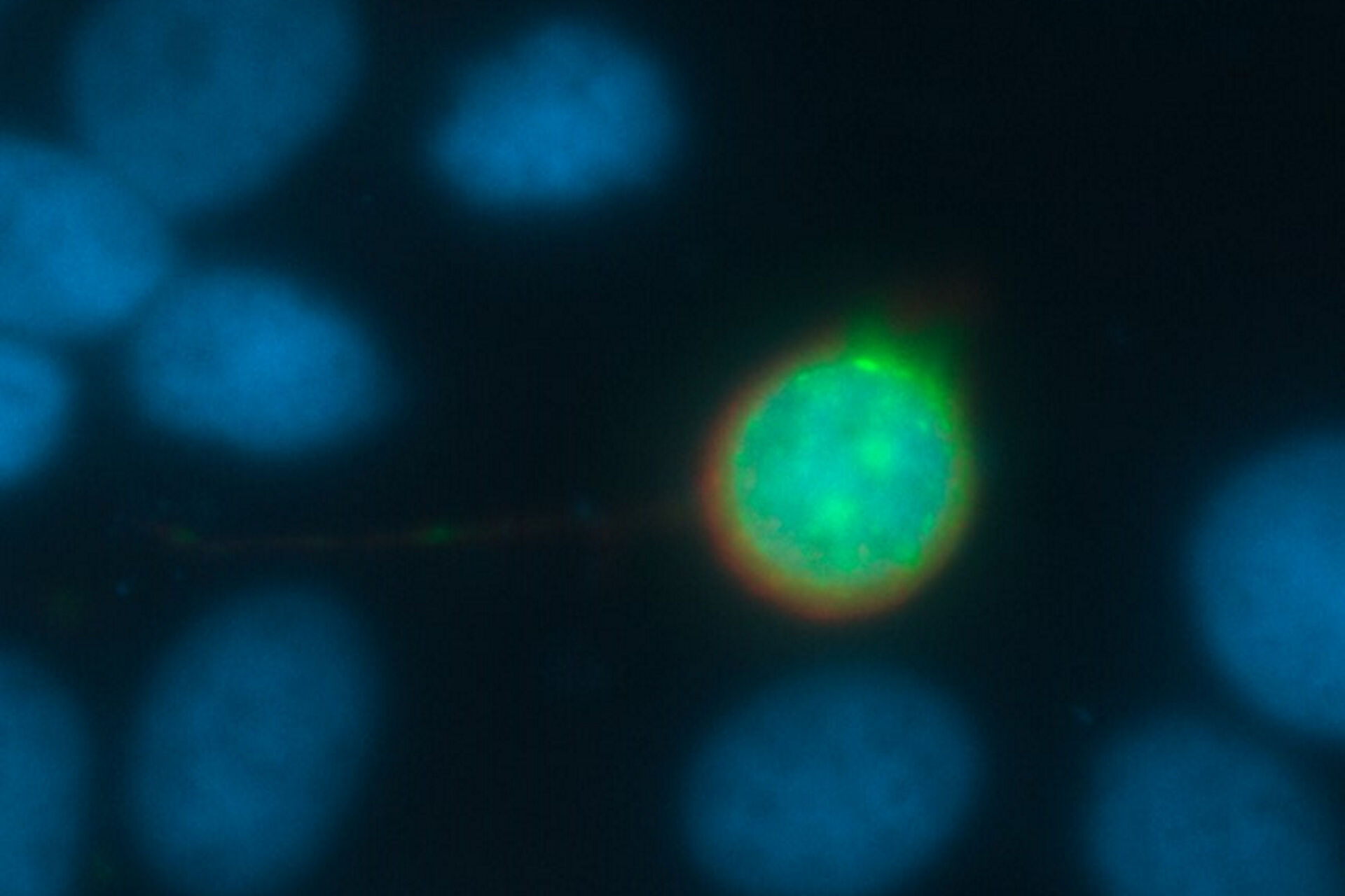
Every fluorescence microscope user wants to have as much detailed information of the structure of interest as possible. The problem here lies in the limited capability of an optical system to produce a realistic picture. All light sources, such as a fluorescent protein within a specimen, emits scattered light. In practice, the scattering can lead to a blurry signal, depending on the thickness of the specimen. To overcome this problem, different approaches have been developed.
Eliminating out-of-focus light with pinholes
Confocal microscopy excludes the out-of-focus information by using a sophisticated positioning of pinholes in the excitation and emission light pathway [1]. This approach leads to a large vertical (z) resolution (small focal depth) and eliminates the out-of-focus signal contribution. Due to the small confocal volume for each visualized point in the specimen (optical sectioning) [1,2], the final image is created after all optical sections of the specimen are collected. So, the benefit of higher resolution is offset by a longer image acquisition time.
Widefield microscopy
A conventional widefield microscope has no pinholes and collects both in-focus and out-of-focus light signals [3]. It offers fast image acquisition, but lower resolution.
Historical solution: Sharper images with deconvolution
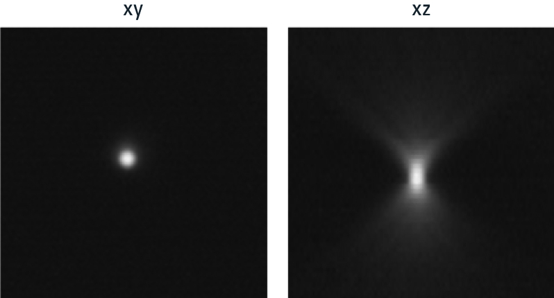
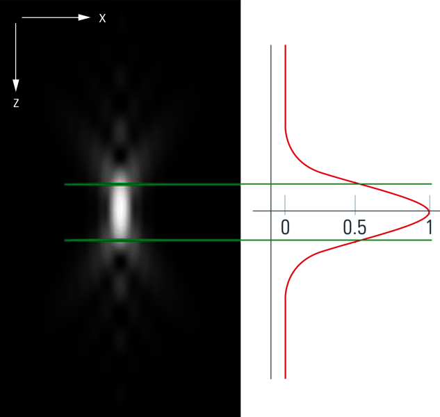
To understand how to solve this problem of blurriness in a widefield image, it makes sense to start by looking at a very small sample, like a round latex bead, which has dimensions below the resolution limit of the microscope. Observing this 3D fluorescent specimen with a microscope in the lateral (xy) orientation, the observer sees the projection of a glowing point with a blurry surrounding (Fig. 1). An acquisition of a z-stack results in the following depiction: The side view of the bead resembles two cones standing on top of each other's apex. This result is due to stray light which is recorded during the z-stack acquisition. This "false" information can be subtracted from the signal data so that an image truly representative of the actual bead is produced. This subtraction is done with the help of a mathematical calculation known as deconvolution [4,5].
Point Spread Function (PSF)
To understand the basics of this procedure, it is necessary to introduce a special term which is very often utilized when it comes to deconvolution: the point spread function (PSF) [4,5].
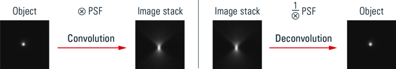
In principle, the distortion phenomenon seen in figure 1 stems from the limited ability of an optical microscope to generate a representative image of a point light source. The light signals which pass through the lenses of the microscope are distorted depending on the settings of the optical system, the wavelength of light, the objective and its numerical aperture (NA), the refractive index of the immersion media, and other parameters. The result of all these influences – concerning their effects on the final image produced by an optical system – is described as a point spread function (figures 2A and 2B). In physical terms, one can think of the sample as convoluted (folded) with the PSF. At the same time, by knowing the PSF, it is possible to “unfold” the sample from the PSF. This “unfolding” is called deconvolution.
The question now is: how can one determine the PSF? The PSF is commonly estimated via a calculation. When information like the excitation and emission wavelength peaks and numerical aperture (NA) of the microscope objective is provided, a theoretical value for the PSF can be calculated with a computer algorithm.
Beyond deconvolution: Computational clearing
The THUNDER Imager technology from Leica Microsystems delivers in real time images of thick biological specimens with sharp contrast, free of the haze or out-of-focus blur typical of widefield systems. It uses an approach called Computational Clearing that goes beyond deconvolution methods [6]. Computational Clearing detects and removes the unwanted signals from out-of-focus regions in real time and clearly reveals the desired signals from the in-focus region of interest. It distinguishes between the out-of-focus and in-focus signals via the difference in size of the specimen features. The feature size and all relevant optical parameters are automatically taken into account. The Computational Clearing method successfully visualizes details with sharp focus and contrast for specimens that are usually not suitable for imaging with standard widefield systems. Also, it can be combined with image restoration methods. To know more about how the THUNDER technology and Computational Clearing work, refer to this technology note.
 and phalloidin (magenta), imaged using Viventis SCAPE; scale bar 50μm. Courtesy of Marina Cuenca and Heleen Jungen (Dayton lab), EMBL Barcelona.")
.")

