
Introduction
Well established since the beginning of the last century [1], the traditional approach for the identification of firearms used to commit crimes requires the examination of the class characteristics, macroscopic marks derived from design factors related to a limited group of weapons that can be found on the firearm evidence under investigation [2,3].
These toolmarks indicative of the type of weapon used to commit a crime are normally investigated with optical instruments, first with the stereomicroscope for the preliminary check where the three-dimensional view with an enlarged image is obtained [4] and then the toolmarks are compared with the comparison microscope which allows to compare the features of the find with the homologous signs found on the reference samples that are fired with a seized firearm suspected of being used the offense or capable of producing the same type of marks found on the evidence.
If all types of class characteristics match, then examiners proceed to compare the individual characteristics, i.e. the micro-traces produced by the random imperfections or irregularities that characterize the part of the gun that goes into contact with the ammunition and result from numerous factors, like wear and tear of the gun, incorrect maintenance, type of ammunition fired, among others [5-7].
When comparing individual characteristics, forensic examiners look for repetitive marks present on the evidence and that should be present in the same location, have the same shape, and be detectable with the same imaging parameters on the reference samples [7,8]. This optical process, traditionally considered more qualitative, allows the firearm examiner to answer two of the questions generally asked, such as, the type of gun used (make and model) and whether a particular gun under consideration was actually used [3,9]. However, it does not provide further information about the shooting mode, for example, when it is necessary to discriminate between murder, suicide, or accidental discharge, neither between contradictory reconstructions of events (such as attempted murder and accidental discharge), particularly in the absence of eyewitness accounts. The topographic analysis allows objective data to be extrapolated that can be used by forensic examiners to deepen the study of toolmarks (class characteristics and uniqueness of the weapon) and, within certain limits, to support investigations for the reconstruction of the criminal event through the study of the variability of the surface morphology and ammunition impression depth generated by the different shooting conditions and circumstances [10], which is otherwise difficult to communicate to a jury.
A number of different methods have been developed to measure surface topography. They may first be classified into 3 categories - line-profiling, areal-topography, and area-integrating methods - as described in the standard ISO 25178 [11,12]. In this article, the line-profiling and areal-topography methods will be emphasized. For both methods, surface profiles or topography images, represented mathematically as z(x) or z(x, y), respectively, are acquired by probing the surface heights with high lateral resolution. The area-integrating method, where a single measure of surface texture over an area is estimated by probing the entire area at once, has not been used for firearms research or identification [11,12].
Precise topography measurements are making quantitative analysis of firearm identification evidence possible. Eventually ballistics identification will likely evolve from qualitative image comparison to quantitative topography measurements [13,14].
Methods
Firearms
For this experimental work, 3 types of 0.357 magnum caliber revolvers with a barrel length of 6 inches (15.2 cm) were used. The firing pins were built into the hammer on 2 of the revolvers and the firing pin and hammer were separate (known as an inertial firing pin) on the remaining revolver.
Ammunition
The ammunition used was Fiocchi type TCCP, 0.357 magnum caliber, lot no. 5904005-005, and with a bullet mass of 158 grains (grs). The consistency of ammunition features, like the thickness, composition, and hardness of the shell head , was accurately maintained for the study as these have a significant influence on the degree of flattening of the primer capsule and structure and depth of the firing pin impression [15].
Shooting ammunition
Shots from the revolvers were made into swinging cases filled with cotton. The chamber of the cylinders of each revolver was left unchanged, but the orientation of the revolver during shooting was varied in 3 ways: downwards vertical, upwards vertical, and horizontal. Vertical means after shooting the bullet traveled perpendicular to the ground surface, either going towards it (downwards) or away from it (upwards), and horizontal means it traveled parallel to the ground (essentially a constant height above the ground).
Topographic Data
A FS C motorized forensic comparison macroscope from Leica Microsystems was used to acquire the image data from the cartridge primer of fired and unfired ammunition. The topographic image data was acquired in multi-focus imaging, also known as extended depth of field (EDOF), mode. The 3D topographic data was displayed and analyzed with the Leica Map surface imaging and metrology software.
Results
Topographic analysis cartridge primers
Unfired ammunition
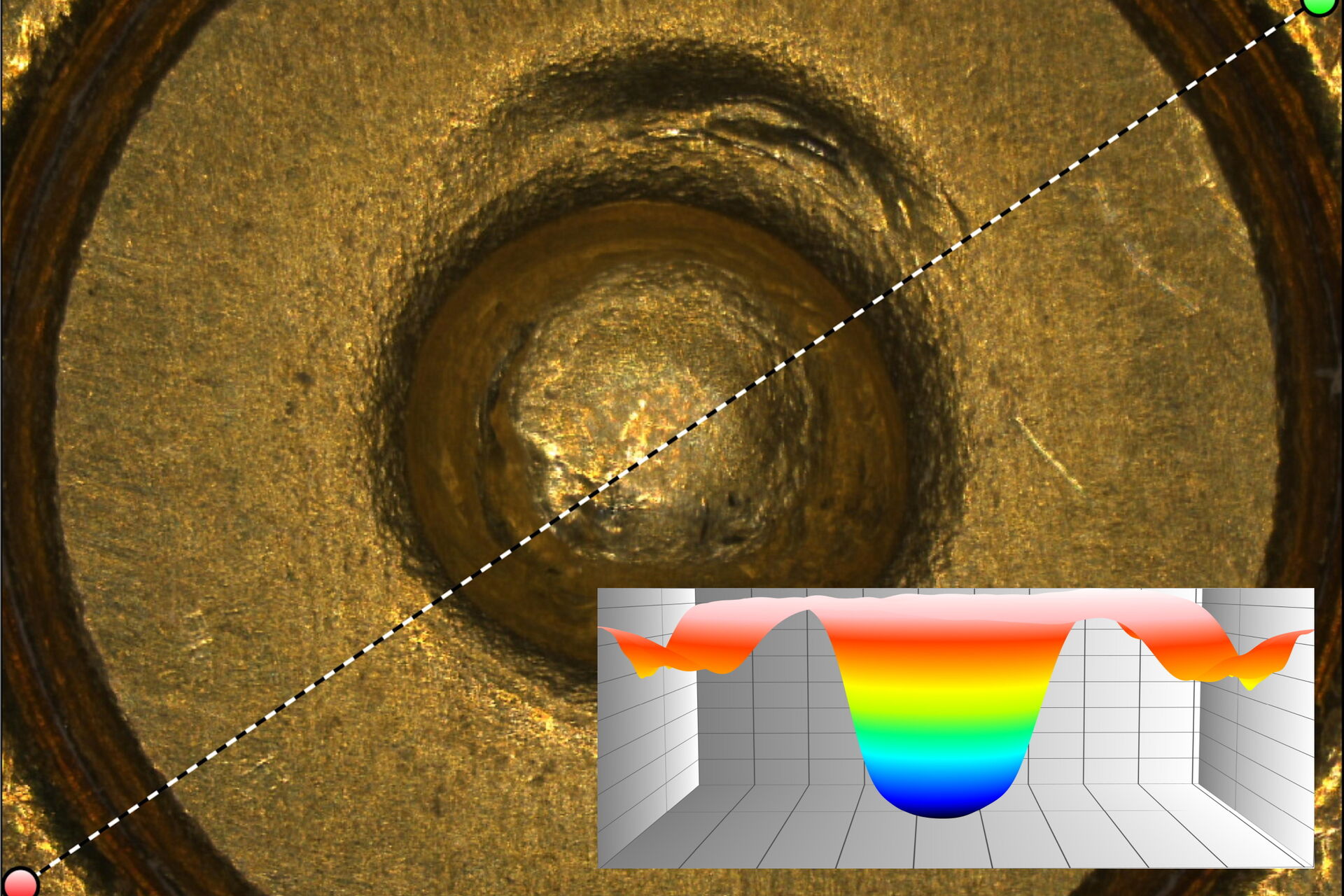
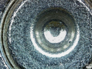
A preliminary analysis of unfired cartridges is necessary to exclude any inherent protrusions of the primer cup or not correct fitting cartridge cases as a reference for the extrapolation of the depth of the percussion impression [15]. The ammunition analyzed did not show any such irregularities. The contour profile of an unfired cartridge primer surface (refer to Fig. 1) can used as a reference for the determination of the firing pin impression depth after firing. Also, the firearm must be studied for unique characteristics like firing pin hole marks (refer to Fig. 2).
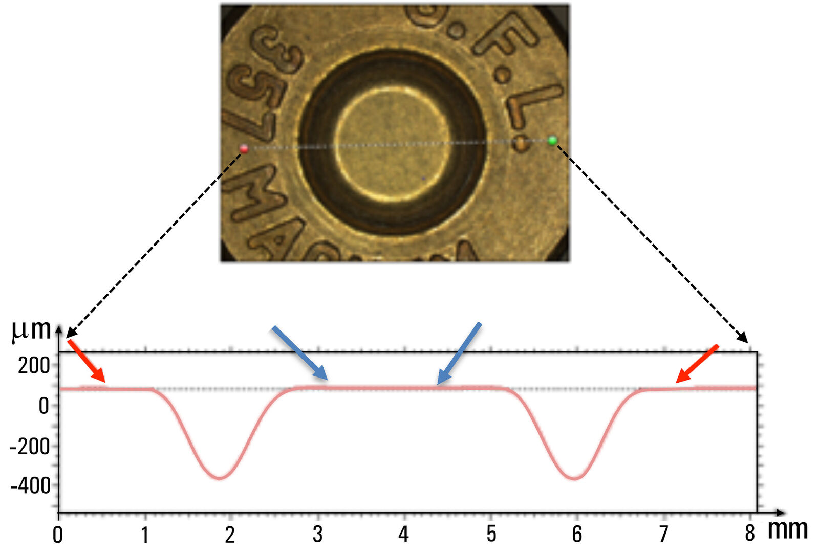
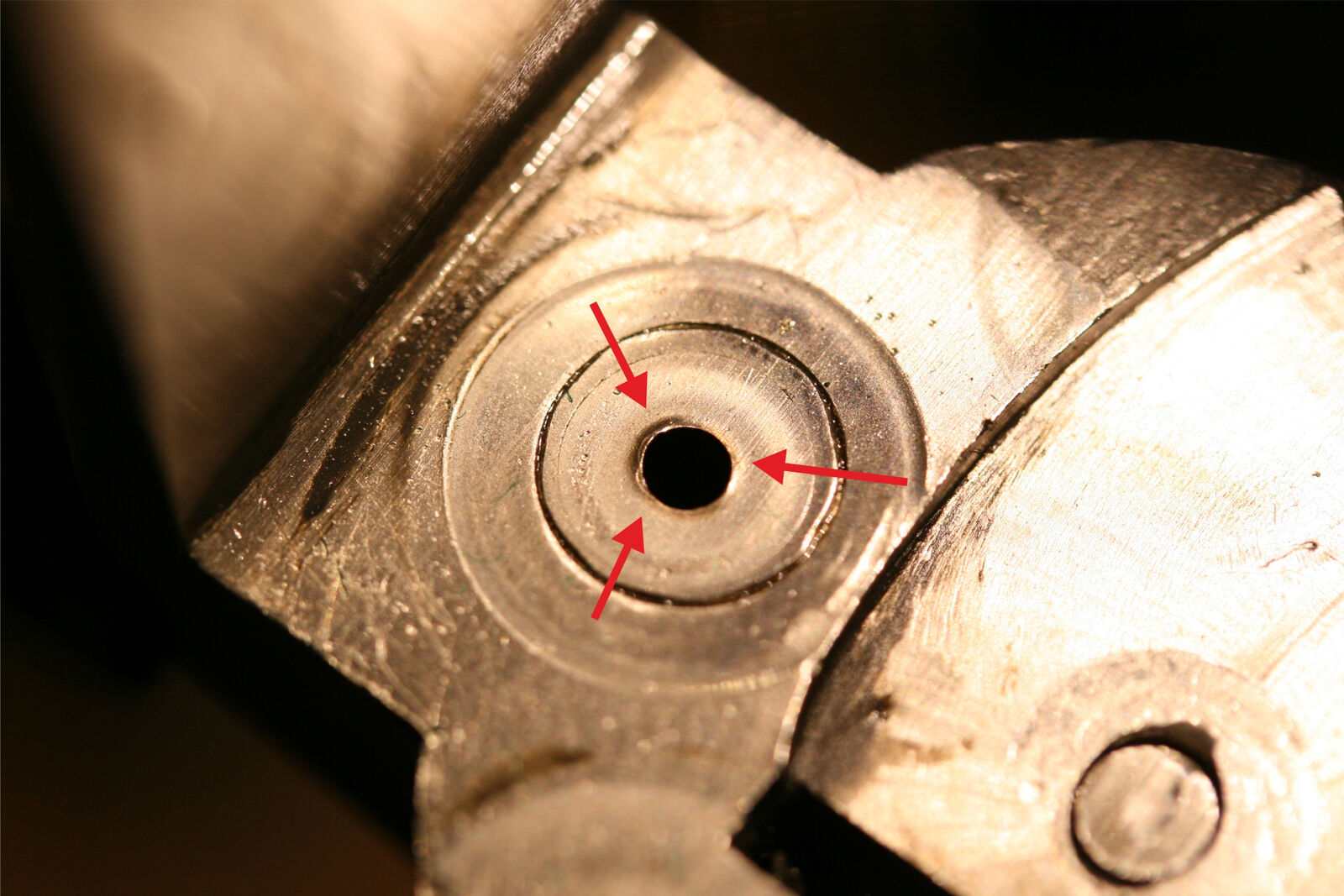
Fig. 2: Micrograph of the breech face of weapon 1. The red arrows indicates the firing pin hole mark, a unique characteristic of this weapon. The mark is produced by the backward flow of the metal of the priming cup into the firing pin hole [16].
Fired ammunition
Optical microscope images of primer cups (refer to Fig. 3) after being firing in the 3 different orientations show markings which are unique characteristics of the firearm used.
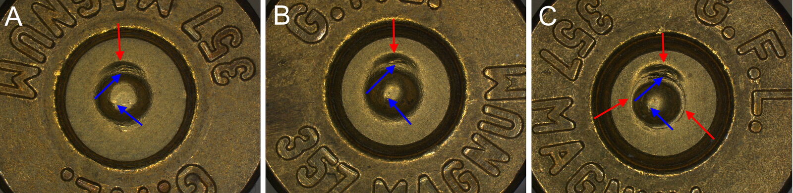
It is important to note that the results of this study do not change the conclusion that a revolver’s firing pin leaves unique marks on the primer regardless of the position of the weapon when fired.
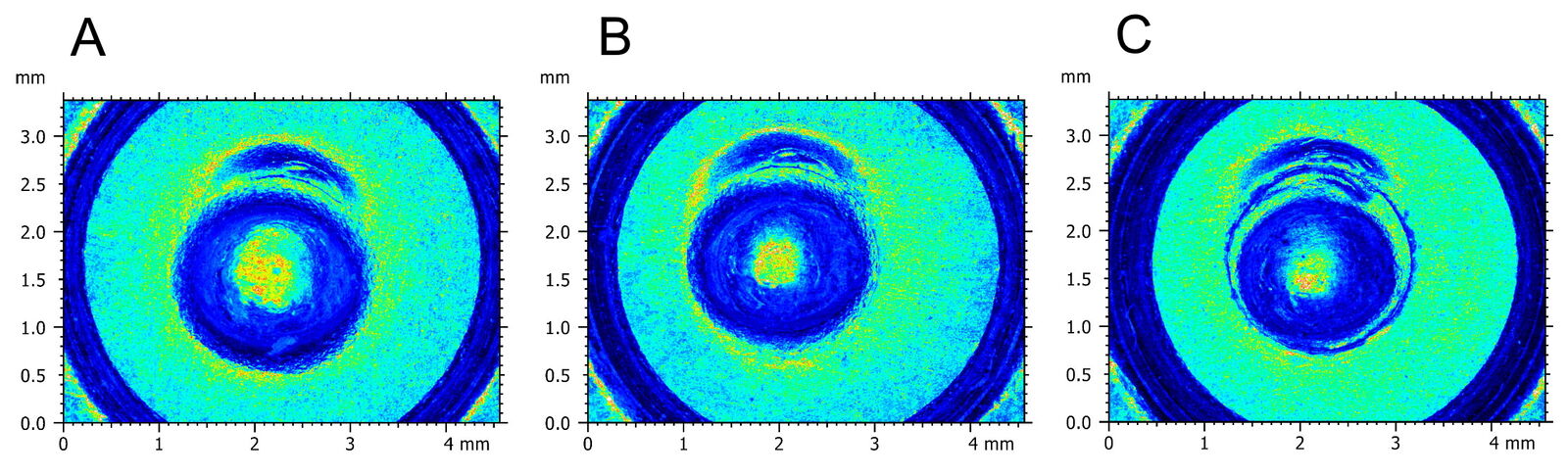
A recurring morphological aspect of all the cartridge samples examined for the different shooting conditions is topographically highlighted in figure 4. This aspect concerns the different apex morphologies of the firing pin impressions which, for factors not dealt with in this study, correlate with the different firing orientations.
As shown topographically, the apex of the firing pin impression obtained by shooting downwards (refer to Fig. 4A) is wider and flatter. It can be considered as distinctive from apexes of the shots that took place in the horizontal and vertical orientations (refer to Fig. 4B and C) which have similar widths. Further investigation is needed to evaluate if this anomaly physically correlates with a specific event, such as for the case in question with the different firing positions.
Topographical data were acquired for each cartridge sample in the manner shown just below (refer to Fig. 5). Then data for each case were analyzed and compared. Data from shots fired horizontally were used as a reference.
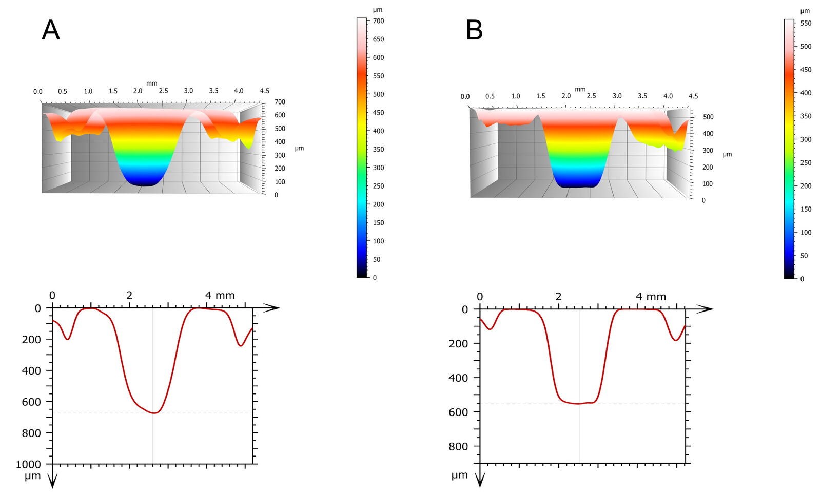
Shot fired horizontally (Fig. 5A) | |
Profile Parameter | Deepest point of Profile |
X | 2.45 mm |
Z | 691 µm |
Number of data points along contour (X) = 736 points | |
Shot fired downwards (Fig. 5B) | |
Profile Parameter | Deepest point of Profile |
X | 2.63 mm |
Z | 562 µm |
Number of data points along contour (X) = 790 points | |
Table 1: Data for the deepest point of the topographies measured for the cartridge primer surfaces seen in figure 5 above.
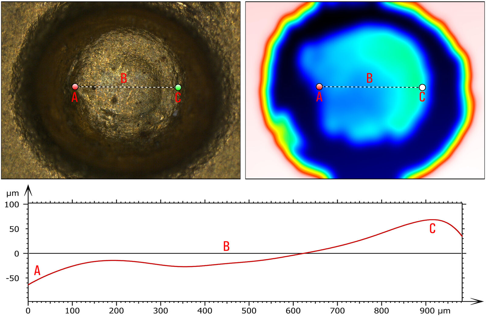
The apex of the firing pin impression can be influenced by plastic deformation to various degrees which, if not carefully evaluated, can compromise the correct extrapolation of the depth values by the user analysis. It can also interfere with the microscope optical sensors during topographic image acquisition if shadowed areas are present due to the deformation.
Figure 6 shows an example of deformation found at the apex of the percussion imprint imparted on the primer cup by the firing of firearm 1 in the horizontal orientation. As can be seen in the profile curve, different depths can be found within the same area.
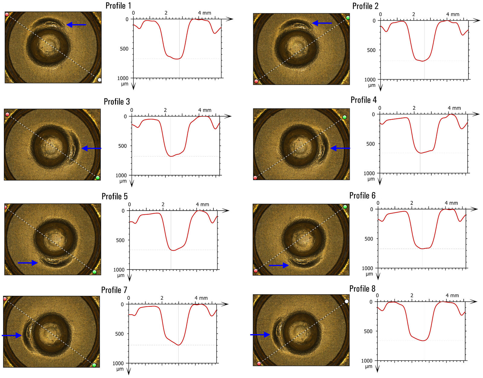
The depth of each individual sample was obtained from the arithmetic average of 8 measurements extrapolated according to a protocol designed to limit any acquisition errors induced by irregularities. A method considered effective involves the extrapolation of two orthogonal profiles for each case which are obtained by rotating clockwise a particular characteristic, used as a reference point, that is highlighted on all samples regardless of the orientation of the weapon during firing.
Figure 7 summarizes the acquisition phases of the 8 profiles from which the maximum depths were obtained. By way of example, the apex of the firing pin impression shown in figure 6 shows plastic deformation that determines the variability in the depth values. It is important to underline that the acquisition lines are not chosen for a geometric symmetry, but rather for a passage over the deepest point of the firing pin impression.
A t-distribution statistical analysis was carried out in order to compare the 3 sets of impression depth measurements relative to the 3 firing positions, i.e. with the weapon held parallel to the ground (standard firing mode), oriented upwards, or downwards [10].
Comparison of the impression data for the 3 cases shows that the p values for all 3 possible pairings (horizontal versus upwards shot, horizontal versus downwards shot, and upwards versus downwards shot) were less than 10-5 [10]. Because the p values are much less than 0.01, this result means that there is much less than 1% overlap of the data for each pair above, so the differences are highly significant.
In particular, the results have confirmed that there are significant statistical differences between the 3 sets of impression depths, relative to the three shooting positions [10].
Another topographic parameter considered in this study is the degree of flattening of the primer cap [10].
Forensic investigators have known for decades that the pressure generated inside a case after firing expands both sides of the case and pushes the base of the primer against the breech face. A consequence of this interaction is a flattened primer base where the degree of flattening depends on the pressure developed in the cartridge. The study of the variability of the degree of flattening of the primer capsule is considered to be a good method to estimate whether the ammunition fired from the same weapon in different orientations developed higher or lower pressures. In particular, when the ammunition develops a lower pressure upon firing, there is less flattening of the cap and the recess of the firing pin is more rounded at the edges and less deep compared to a standard pressure case. In the case of high pressure in the cartridge upon firing, the flattening of the cap is much more pronounced and metal accumulates around the edge of the firing pin cavity [7]. This evaluation, which to date is carried out by holding the back of the cartridge against the light and observing it with the naked eye, however, requires a lot of experience. The extrapolated qualitative data, which depends on the subjective judgment of the observer, is not admissible as evidence in court.
New forensic studies have shown, through the crossing of instrumental data, that the pressure in a cartridge fired by revolvers also varies with the orientation of the weapon during firing [16].
In figure 8 below, the topographies of cartridge primer surfaces being fired from weapons held in a downward (Fig. 8A), horizontal (Fig. 8B), and upward (Fig. 8C) orientation are shown. A contour profile extracted from each topography along the line indicated is also shown. From these topography data, it is clear that the primer cup surface of the cartridge fired upwards shows the most flattening, while downwards shows the least, demonstrating topographically the correlation between the pressure developed inside the ammunition and the position of the weapon.

Conclusions
From the topographical analysis carried out on the fired and unfired ammunition using the 3 revolvers for this study, the following about impressions (craters) on the cartridge primer caused by the firing pins can be concluded:
Flattening of the primer cup of a cartridge for the 3 orientation of shots fired:
- Vertically upwards shows the greatest flattening;
- Horizontally shows more flattening compared to downwards, but less than upwards; and
- Vertically downwards shows the least flattening.
The depth of the primer impression for:
- Shots fired upwards is deeper compared to shots fired horizontally;
- Shots fired downwards is shallower compared to shots fired horizontally.
Rigorous analysis of primer cup flattening and impression depth with a FS C comparison macroscope and the Leica Map software enables investigators to make objective, reliable conclusions about these forensic parameters [10].
The fact that both topographic and conventional optical image analysis can be performed with a single instrument, the FS C comparison microscope, helps to reduce costs as it avoids the need to have sample analysis done by external laboratories [17]. Sample analysis by external parties also carries with it the risk of the evidence being accidentally altered [17].
The results indicate that topography data of ammunition can help forensic examiners make more thorough investigations of ballistic evidence, enabling routine quantitative analysis instead of merely qualitative image comparison [12,13].
")

