
From Anton van Leeuwenhoek to compound microscopes

Since the invention of glass by the Romans in the first century, people discovered that a magnification effect was created by round-shaped pearls of glass. Later on this effect was scientifically investigated and further developed, resulting in the simple magnification glasses of the 16th and 17th centuries, e.g., those invented by Hans and Zacharias Jansen or Anton van Leeuwenhoek. Historically, this was the hour of the birth of microscopy.
By definition, the “microscope” is an instrument that magnifies objects that are not normally resolvable by the human eye, and so these single lens tools were already – microscopes (s. Figure 1 top). Nowadays we think of something different when we talk about a microscope. This is due to the fact that people soon realized that the combination of two separate lenses (or lens systems) in a row is a more effective visual tool than a single lens.
To describe such a set-up the term “compound microscope” was created. Compound microscopes consist of an objective magnifying the specimen and an eyepiece (respectively two) magnifying the image produced by the objective (s. Figure 1 middle).
Introduction of infinity optics

The distance between the objective shoulder and the ocular shoulder is called mechanical tube length (s. Figure 1 middle). For standardization this value was set to 160 mm by the Royal Microscopical Society in the 19th century. Over the years this design turned out to have some drawbacks. Adding additional optical elements into the light path, such as prisms for Differential Interference Contrast (DIC), polarizers, etc., changed the effective tube length and introduced aberrations, which had to be accepted, or corrected with the addition of other hardware components.
For this reason the microscope manufacturer Reichert started to experiment with so called infinite optics in the 1930’s, and this technology was later adopted by all other microscope companies. Objectives of these infinite optical systems project a specimen image to infinity, meaning that all light rays derived from a single point of the specimen emit from the objective in a parallel way. Those rays within the center of the specimen (and the objective) run parallel to the optical axis. Those outside the center of the specimen run parallel to each other, but not to the optical axis.
The virtual image produced by an infinity-corrected objective has to be captured by an additional lens – the tube lens – to bring it to the front focal point of the eyepiece lens (s. Figure 1 bottom). This approach enables the addition of optical instruments such as DIC prisms into the “Infinity Space” between the objective and the tube lens without influencing image quality. Neither location nor the focal point of the image is altered (s. Figure 2).
Advantages of infinity optics
Several contrast methods require the introduction of special optical components into the microscope’s light path. For example, prisms and polarizers for DIC, or dichroics and filters for fluorescence microscopy, are indispensable for the relevant technique. Introducing such optical components between the objective and the eyepiece of a microscope with finite optics alters the effective tube length and introduces spherical aberrations. These can be corrected with the introduction of additional optical elements, but at the expense of diminished light intensities or increased magnification.
In comparison, a microscope with infinity-corrected optics can hold extra equipment for contrast methods without optical damage by introducing them into the Infinity Space. Devices installed in the infinite light path alter neither imaging scale nor location of the intermediate image. This is due to the fact that all light rays coming from a single point of the specimen will leave the objective in a parallel way.
Overall image quality is not the only thing that benefits from infinity optics. Since the magnification doesn’t change when shifting different optical devices into the infinite light path, one can easily compare the exact same sample using different contrast methods. For example, specimens can be imaged in DIC and fluorescence simultaneously (s. Figure 3).
 and fluorescence images (middle) can be received simultaneously (right).")
With a few exceptions, most microscopes have an objective revolver where different objectives can be installed and changed according to the desired magnification. Parfocality allows users to switch between objectives without needing to refocus the specimen. With infinity optics parfocality can be maintained even if additional optical instruments are added to the Infinity Space.
How to get even more devices into the infinite light path
Optical microscopy is still an evolving field. Development of new techniques requires access to the microscope’s light path, for example to include additional light sources or laser devices. Fluorescence Recovery After Photobleaching (FRAP), for instance, needs a laser to bleach fluorophores (s. Figure 4). Digital Mirror Devices, another example, are used for optogenetics, uncaging, and photo-bleaching/activation.

The introduction of Infinity Optics paved the way for these methods since it simplifies the coupling of the necessary components into the microscope’s light path via the Infinity Space.
By now new approaches have been invented to get additional devices to the infinite light path. Technically there are two ways to enter the Infinity Space: Either in the imaging path between objective and tube lens, or in the illumination path between the objective and the light source (s. Figure 5). Access through the imaging path has the advantage that dedicated modules, for example motorized fast filter wheels and shutters, can be introduced into the microscope very comfortably.
Nevertheless one should keep in mind that the Infinity Space – although its name would suggest otherwise – cannot be extended endlessly by stacking modules into the microscope. The reason is that only light rays coming from the center of the specimen are parallel to the optical axis.
Off-centered light rays coming from one point of the specimen are parallel to each other but will strike the tube lens in a certain angle. Logically enlarging the imaging path between objective and tube lens will result in a loss of light. More precisely, this induces vignetting and will reduce the field of view.

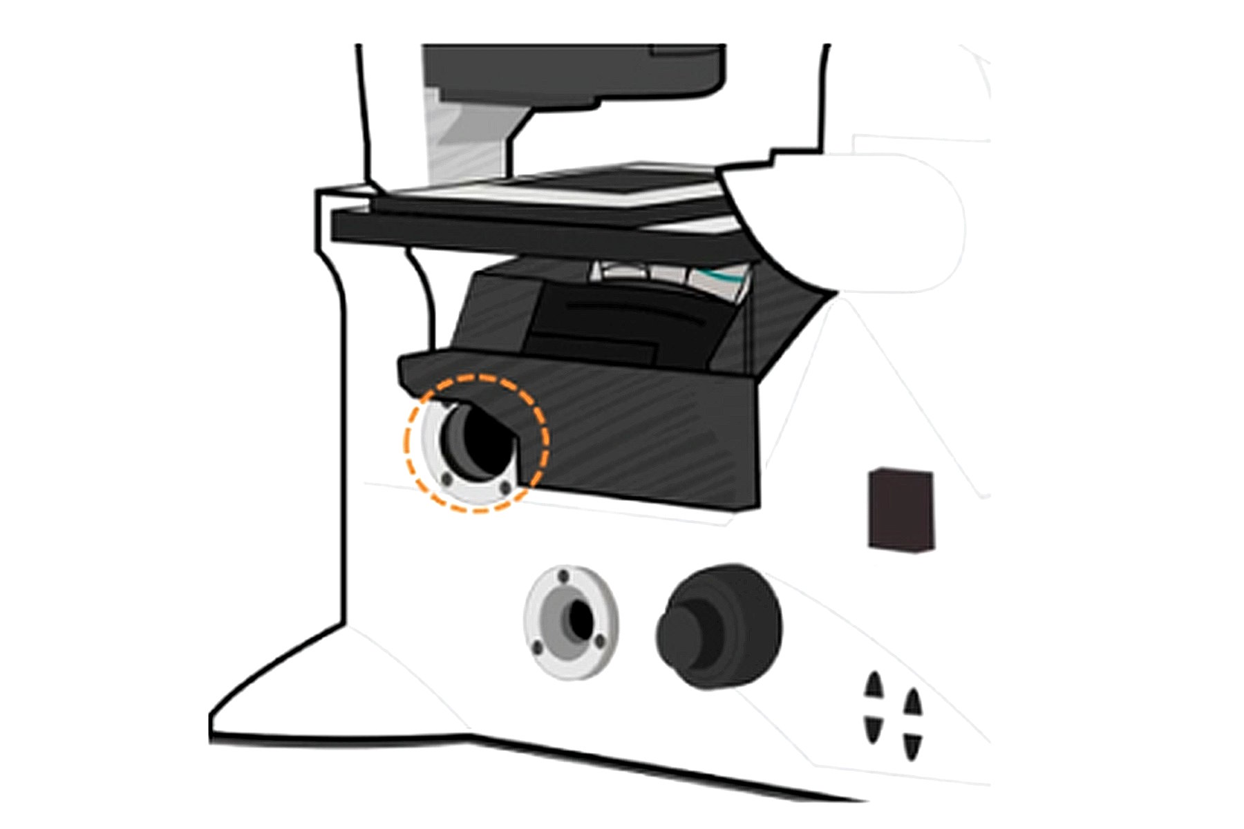
Video: The Leica DMi8 Infinity Port

Entering the Infinity Space through the illumination path of the microscope, such as through the Leica Infinity Port, circumvents the issue of elongating the imaging light path (s. Figure 6). Beyond preserving image quality, this feature has the advantage of being more universal. With the correct adapter at hand, any device can be attached to the microscope. Homebuilders, in particular, can build and connect their own devices, 3rd party, and Leica instruments, to create a customized imaging solution.
Summary
The introduction of infinity-corrected optics considerably improved the functionality of the modern microscope. The necessity to correct aberrations introduced by prisms or other optical instruments needed for contrast methods is a thing of the past. Besides improved ease-of-use, infinity optics allow the simultaneous coupling of multiple light sources into the microscope.
Leica’s Infinity Port enables direct access to the infinite light path of the microscope stand, circumventing problems that are created by stacking methods. This opens the door for researchers to easily connect additional optical devices without sacrificing image quality and to keep pace with the latest microscopy trends.
This article is also published in: Optik & Photonik, Volume 11, Issue 1, pages 34–37, February 2016;
DOI: 10.1002/opph.201600002.
 and oblique (right) brightfield illumination using a Leica compound microscope. The defect on the wafer surface is clearly more visible with oblique illumination.")