
Fluorescence and Microscopy
Fluorescence occurs either as autofluorescence of biological and inorganic structures or so-called secondary fluorescence after a treatment of the specimen with special dyes (fluorochromes, fluorescent markers) [1-3]. To perform fluorescence in a microscope the following requirements have to be met: intense light sources (LED or gas arc lamps), adequate transmission filter systems for accurately selecting the excitation light and emitted radiation, and, last but not least, optical parts suitable for fluorescence, i.e. collector lenses, illuminators, beam splitters, objectives, tube lenses, eyepieces, and camera [4]. Multiphoton fluorescence microscopy with excitation by 2 or more photons of longer wavelength than the emitted light is possible using a confocal microscope system.
Compared to today, Fluorescence microscopy was applied for the first time with the use of transmitted light and darkfield microscopy, due to its limited range of applications at that time. But with its increasing importance for histology, cytology, molecular biology, and immuno-diagnosis, the demand for a fundamental improvement of illumination and observation techniques came up more and more. This demand led to the birth of epi-illumination or incident-light fluorescence microscopy [5].
During the nearly 40 years of development and improvement, this technique became one of the basic tools for routine and research work in biology, medicine, materials science, and industry. The progress made for incident-light fluorescence microscopy was particularly determined by the research work of the Ploem group and its function as trend setter and also by the forward-looking strategy of Leitz (currently Leica Microsystems) in developing the optical instruments required.
This course of development is described in this article.
Early developments in epi-illumination fluorescence microscopy
For a review of the history of fluorescence microscopy the reader is referred to Kasten [6]. Epi-illumination (vertically incident excitation light) was used already by Policard and Paillot [7]. Several instruments were made by Leitz (now Leica Microsystems), Bausch & Lomb, Reichert and Zeiss, which were partially based on suggestions by Ellinger and Hirt [8,9], Singer [10], and Mehler and Pick [11,12]. An early Leitz fluorescence epi-illumination system was described by Haitinger [13]. For more details on the evolution of epi-illumination fluorescence microscopy the reader is referred to Rost [14] and for early applications of incident-light fluorescence microscopy to Hauser [15].
A major contribution to epi-illumination fluorescence microscopy was the introduction of a dichromatic mirror for incident illumination with ultraviolet (UV) light by Brumberg and Krylova [16]. Epi-illumination has definite optical advantages. Unlike transmitted illumination, where the condenser and the objective have independent optical axes which must be perfectly aligned, the objective functions both as a condenser and as a light-collecting objective, avoiding all alignment problems. The separation of fluorescence emission from the excitation light, using a dichroic beam splitter, is much easier than with transmittted light fluorescence microscopy, These possibilities did, however, not lead to a general acceptance of epi-illumination for routine fluorescence microscopy by microscope manufacturers. The main reason for this lack of interest could have been that transmitted-light darkfield UV excitation gave already excellent results in most applications of fluorescence microscopy [17]. Its replacement by UV epi-illumination would not have given significant advantages. The use of transmitted light using a darkfield condenser remained the industry standard until the late sixties.
The rapidly growing interest in molecular biology, however, led to the development of many monoclonal antibodies for the detection of important macromolecules in the cell. To study the detailed morphological location of several macromolecules in cellular organelles, fluorescent markers with different colors were increasingly used. UV excitation – as used traditionally for fluorescence microscopy – was not optimally suited for detecting multiple fluorochromes simultaneously in a cell.
Around 1962 Ploem started work in collaboration with Schott on the development of dichroic beamspitters for reflection of blue and green light for fluorescence microscopy using epi-illumination. At the time of his first communication in 1965 and publication on epi-illumination with narrow-band blue and green light [18], he was not aware of the development of a dichroic beam splitter for UV excitation with incident light by Brumberg and Krylova [19]. Neither was the Leitz company, from which he obtained an "Opak" epi-illuminator with a neutral beam splitter. This illuminator had to be modified so that a slider could be put in the incident-light path containing four dichroic beam splitters for UV, violet, blue, and green excitation light. This device, developed at the University of Amsterdam, permitted the easy exchange of different dichroic beam splitters in the incident-light path (Figure 1a). The wavelength of the excitation light could be easily and rapidly changed.

Soon it became clear that excitation with narrow-band blue and green light opened optimal possibilities for the detection of the widely used immunofluorescence labels fluorescein-isothiocyanate (FITC) and tetramethylrhodamine isothiocyanate (TRITC). The use of blue and green excitation also minimized autofluorescence of tissue components, an undesired effect encountered with conventional transmitted illumination using UV light. FITC could now be excited with narrow-band blue light (using a band-interference filter with a half width of 16 nm), close to the excitation maximum at 490 nm (long blue wavelength), with clear observation of the green-fluorescence-peak emission at 520 nm. Autofluorescence of tissue components was minimized (Figures 2a and b) resulting in a high contrast.
 and epi-illumination using narrow-band blue (490 nm) light (B).")
Excitation of FITC near its excitation maximum enabled such an efficient excitation that even a mercury high-pressure arc lamp, having no strong emission peak in the blue-wavelength range, could be used. Furthermore, epi-illumination with a green-reflecting dichroic mirror enabled for the first time the excitation of Feulgen-pararosaniline with the strong mercury emission line at 546 nm (Figures 3a and b).
 and epi-illumination with narrow-band green light (B).")
In his second publication on the multi-wavelengths epi-illuminator, describing a Leitz prototype with four dichroic beam-spittters (Figure 1b), Ploem [19] acknowledged the contribution of Brumberg and Krylova [16]. The inaccessibility of Russian research at that period of time and the absence of any major industrial development of epi-fluorescence microscopy in Russia or East Germany was the reason that Leitz had not been aware earlier of such a development. The possibility to introduce epi-illumination with UV light, although useful for several applications, had not been a motive for a new technological development at Leitz, since they had already excellent transmitted darkfield-UV excitation available. However, the increasing worldwide use of routine immunofluorescence microscopy in medical-diagnosis and molecular-biology research could benefit from the new epi-illumination using narrow-band excitation with blue and green light. Because standard high-pressure mercury arc lamps could be used, this seemed to be a practical proposition.
Subsequently, Leitz developed a novel multi-wavelength fluorescence epi-illuminator (PLOEMOPAK) with four rotating dichroic beam splitters for UV, violet, blue, and green light [21]. In successive generations of Leitz illuminators (containing four dichroic beam splitters), barrier filters and a rotating turret for excitation filters were added. Finally, an elegant epi-illuminator was constructed by Kraft [20] containing multiple sets of an excitation filter, a dichroic beam splitter, and a barrier or emission filter, mounted together in a filter cube or filter block (Figure 4).
 for fluorescence microscopy containing an excitation filter, dichroic beam splitter, and emission (barrier) filter.")
Because this illuminator permitted the filter cubes to be rapidly turned into the optical path, multi-wavelength illumination of the same section of tissue became practical. Moreover, the four filter cubes in the illuminator could be exchanged by the user (Figure 1c). Different sets of four filter cubes could be assembled, chosen from many filter cubes, containing combinations of excitation, barrier filters, and dichroic beam splitters, developed for different applications. Following suggestions by Ploem, Leitz also produced an inverted microscope with epi-illumination (Figures 5a and b). For a review of the PLOEMOPAK illuminator for multi-wavelength fluorescence microscopy, the reader is referred to a review by Pluta [22].
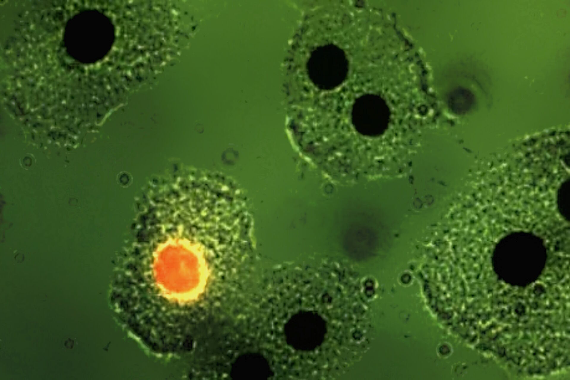
 Leica inverted fluorescence microscope with multi-wavelength epi-illuminator. b) Terasaki® plastic tray with human lymphocytes after a fluorescence cytotoxicity test for transplantation research imaged with epi-illumination and an inverted microscope.")
The Leitz filter-cube system was so efficient that even today similar types of filter cubes are still used by most microscope manufacturers for multi-wavelength fluorescence microscopy. This development finally led to the development of automated multi-wavelength fluorescence epi-illuminators accommodating eight filter cubes for various wavelength ranges (Figure 5c). When switching between filter cubes, pixel shift on the computer monitor is avoided or stays below the resolution power of a 35 mm film due to a 0-pixel shift technology. This illuminator is also used for fluorescence in-situ hybridization methods (FISH) in the study of chromosomes.
Ploem [23-27], van der Ploeg and Ploem [28], and Nairn and Ploem [29] further explored the filter combinations that had to be developed for many biomedical applications. This was done in collaboration with Schott and Leitz. Rygaard and Olson [30] developed a novel shortwave-pass high-transmission interference filter with a very high transmission for blue light and a sharp cutoff of wavelengths longer than 490 nm.
Ploem [31] combined this short-pass (SP) filter with a 1 mm Y (yellow) 455 filter from Schott which blocked UV excitation and suggested the development by Balzers of a similar filter (SP 560) for excitation with green light and another one for excitation with violet light (long pass [LP] 425). The latter filter was applied in the investigation of neurotransmitters [24]. In Figure 6a and b the resulting blue fluorescence can be observed.
![a) Mesenterium of a rat with the small blood vessel surrounded by a blue fluorescent adrenergic (CA) nerve-plexus and yellow fluorescent mast (5-HT) cells. Formaldehyde-induced neurotransmitter fluorescence of CA and 5-HT fluorophores. b) Same tissue and staining as is 6a with epi-illumination and narrow-band violet excitation light (LP 3 mm, Y 400, and SP 425 interference filter), a dichroic beam-splitter for 495 nm, reflecting violet light, and a barrier filter LP 460 nm. This filter cube permittted for the first time the observation of blue fluorescent adrenergic nerve fibers, distinctly different from yellow fluorescent mast cells [25].](/fileadmin/academy/2023/Epi-Illumination_Fluorescence_Update/Mesenterium_of_a_rat_with_and_without_epi-illuminescence.jpg "Mesenterium of a rat with the small blood vessel surrounded by a blue fluorescent adrenergic (CA) nerve-plexus and yellow fluorescent mast (5-HT) cells.")
From the optical industry side, early contributions and reviews on these developments were written by Kraft [32], Walter [33,34], Trapp [35], and Herzog [36].
The main classes of filters used in epi-illumination fluorescence microscopy were defined in (a) the primary excitation filters LP (long pass) and SP (short pass) (in the German literature known as KP filters) and (b) the secondary filters such as barrier filters and emission filters[32]. The latter were also described as fluorescence selection filters which are, for instance, used to limit the observation of the peak fluorescence at 520 nm of FITC. A extensive review on filters for fluorescence microscopy has been given by Reichman [37].
Cormane [38] was the first to demonstrate that narrow-band blue-light epi-illumination of the fluorescent label FITC gave an optimal contrast in immunofluorescence studies of human skin disease. Transmitted-light excitation with UV light used to cause such a strong autofluorescence of elastic fibres in the skin, so that visualization of the fluorescent antibody was severely hindered.
The pioneering work of Leitz in epi-illumination fluorescence microscopy coincided in the seventies with a worldwide increase in the application of immunofluorescence and other molecular biology methods like FISH for medical diagnosis and research. Hijmans et al. [39,40] were the first to demonstrate the usefulness of the new multi-wavelength excitation epi-illuminator for the selective detection of certain classes of immunoglobulins in cells using antibodies conjugated with green-fluorescent stain FITC and red-fluorescent stain TRITC. They applied the two-wavelengths excitation method using blue and green light and the selection of the peak fluorescence of FITC by an emission filter at 520 nm (Figure 7). Brandtzaeg [41] and Klein et al. [42] made similar discoveries in identifying immunologically important cell types, using two-wavelength excitation with the Leitz epiilluminator. In a staining of blood with "rosette" formation, the two-wavelength excitation method using UV and green light can show erythrocytes around a mononuclear cell (Figure 8).


Epi-illumination
In epi-illumination, a dichroic beam splitter is used to deflect the incident light towards the specimen. The spectral characteristics of the dichroic mirrors have been designed in such a way that only the desired excitation wavelengths are deflected downwards through the objective onto the specimen, while the unwanted wavelengths are transmitted by the dichroic mirror and collected in a light trap [20] behind the dichroic mirror. The elimination of this unwanted excitation light results in a significant decrease of stray light and, thus, improves the image contrast. The dichromatic mirror deflects the desired (short wavelength) excitation light through the objective onto the specimen, but is transparent to the longer fluorescence wavelengths. The suppression filter (barrier filter) absorbs (or reflects) the excitation light reflected from the specimen and the lens surfaces of the objective, but is highly transparent to the fluorescence, which can then reach the eyepieces or camera sensor. The efficiency of epi-illumination is related to the fourth power of the numerical aperture (NA) of an objective, serving first as a condenser and then for observation as a light-collecting lens. At the time of marketing the first multi-wavelength epi-illuminators, only high-power objectives (70x, 100x) were available with a high NA (0.95, 1.30). Following suggestions by Ploem [18,19], Leitz was the first manufacturer to produce moderate power objectives like the oil-immersion 40x objective with a NA of 1.30 (Figure 9). This new type of objective, especially designed for epi-illumination fluorescence microscopy, resulted in very bright images permitting short exposure times in routine fluorescence microphotography.
 oil-immersion objective 40x with a NA of 1.30 developed for trial experiments in fluorescence epi-illumination technology")
Optimal filling of the entrance pupil (aperture) of an objective
A problem in epi-illumination fluorescence microscopy has been the optimal filling of the entrance pupil of the objective with an image of the light source. A medium magnification of the light source of approximately 8 times was typical. This result is related to the different arc sizes of the various high-pressure mercury and xenon arc lamps. In addition, entrance pupils of objectives vary considerably, e.g., 3.6 mm for a 100x, NA 0.90 objective and 12 mm for a 10x, NA 0.30 objective. Furthermore, if only part of the arc can enter the entrance pupil, the fluorescence intensity obtained will be diminished. Schönenborn [43] reported on a completely innovative incident-light path in the DM R (HCS) microscopes. The path for epi-illumination has now been designed to allow individual adaptation of the light path to the specific light sources used for different applications. Assuming a Koehler illumination in the incident-light path, the combination of illumination optics and collector is needed to image the light source in the entrance pupil of the objective. For a given objective, the choice of magnification for the light source depends directly on its geometric dimensions. Halogen lamps should be very well adjusted, because the coils of the lamp filament are extremely sensitive to filament maladjustment. Relatively low magnifications are then advisable.
Leica Microsystems has further improved objectives for fluorescence microscopy. The selection of optical glasses with low autofluorescence properties resulted in an enhancement of the image contrast.
A problem of fluorescence microscopy with widefield illumination was that no sharp images could be obtained from relatively thick specimens. This result is due to the unwanted contribution of scattered light from adjacent optical planes which are out-of-focus, when using objectives with a high numerical aperture, to the final microscope image. However, the Leica confocal microscopes can obtain sharp images taken at high lateral and vertical resolution from one or more focal planes within the specimen using optical sectioning.
The color separation of multiple fluorochromes in a specimen has been further improved by spectral analysis. Computer-assisted spectral confocal scanning microscopy has become a powerful tool for fluorescence microscopy in biomedical and materials research. More recently, an imaging microhub, Mica, has become available. It unifies multiple fluorescence imaging modalities, including widefield, confocal, THUNDER, LIGHTNING, multiplexing, and more.
Filter cubes for various applications in molecular biology
The explosion in molecular-biology applications over the last few decade has led to a development of many filter combinations for the various applications. These sets of filters are now mounted in a large variation of filter cubes (blocks). Fluorescence epi-illuminators enable the exchange of 2 to 8 filter cubes by hand-operation or motorized exchange. A comprehensive and detailed discussion of the multitude of applications enabled by the various filter cubes is not given here.
Reflection contrast microscopy (RCM)
The development of epi-illumination microscopy by Leitz also led to a further development: reflection-contrast microscopy (RCM) [44,45]. Reflection-contrast microscopy provides strong signals from specimens stained with routine absorbing immunomarkers, such as peroxidase-DAB, immunogold-silver, and immuno-phosphatase (Figures 10 and 11). Because of the strong signals that can be obtained – the high image contrast and no deterioration of the image by pre- and post-focal images, RCM of thin sections fulfills all the theoretical optical criteria for optimal microscope resolution. The optical results can be defined as high-definition images.
 images of mouse peritoneal macrophages adhering to a coverslip and stained with a monoclonal antibody for surface antigens.")
 of kidney tissue prepared with peroxidase DAB staining.")
The strong reflection of most immunostains used for electron microscopy (EM) provides such a high contrast that this staining can be combined with many classical (absorbing) histochemical stains for important macromolecules that show a moderately strong reflection. The latter stains can often be used to enhance fine morphological orientation and, in many cases, a more precise location of the immunomarker is achieved than with fluorescent markers alone. In addition, such light microscope observations can be confirmed by electron microscopy through examination of a next ultra-thin section (having the same immunostaining) with EM.
 for reflection contrast microscopy, containing a polarizer, a neutral (50 %) beam-splitter and an analyzer.")
With confocal laser scanning microscopy, RCM can be performed without a special objective or other stray-light-reducing optical measures, due to the elimination of stray light by illumination through a pinhole. Most absorbing immunostains give a very strong reflection of laser light and show very limited fading. They often permit the use of a small pinhole size (e.g. 10 µm), which is about five to ten times smaller than can be used with most fluorochromes in confocal fluorescence laser scanning microscopy. Therefore, the use of reflecting immunomarkers can result in a very significant increase in optical resolution. Specimens double-stained with both a fluorochrome and imaged with a Leica confocal laser scanning microscope provide possibilities for examining multiple markers and a reflecting immunomarker.
RCM uses a fluorescence-microscope stand, epi-illuminator, and high intensity light sources, like a gas arc lamps. In the fluorescence epi-illuminator, an extra polarizer filter cube containing a polarizer, reflector, and an analyser must be inserted (Figure 12). Also a reflection-contrast (RC) diaphragm module (containing the central stop system) must be brought in the incident-light path. This RC diaphragm module adapts sliding sets with central stops and/or aperture diaphragms. Furthermore, a special objective developed for reflection-contrast microscopy should be added to the set of microscope objectives.
The contrast of reflected-light microscopy is based on differences in reflection intensities (reflectance). For this type of microscopy, it should be remembered that reflection of light occurs at every optical boundary, that is when the refractive index and/or the absorption index change. For biological specimens showing a reflectance of less than 1% and mostly less than 0.2%, it is almost impossible to obtain a reflected-light image with a conventional microscope, due to the unwanted reflections inside the microscope tube. In reflection-contrast microscopy, a combination of two methods is used to reduce glare due to scattered light. The incident light is made into a ring-shaped cone of light by the insertion of a central stop (an aperture diaphragm provided with a central stop, creating an annular aperture) in the incident-light path at a plane conjugated with the back focal (aperture) plane of the objective. As a second method, unwanted scattered or reflected light is reduced by the use of the "antiflex" method. Light reflected inside the microscope is suppressed by using crossed polarizers, with the result that only the light reflected from the specimen is passed on to the eyepieces or camera sensor. For this reason, an objective is provided with a quarter-wave plate in the front lens. The passing of the light through the quarter-wave plate (downwards to the specimen and upwards after reflection from the specimen) change the polarization direction of the light with 2 x 45° = 90°.
 and phalloidin (magenta), imaged using Viventis SCAPE; scale bar 50μm. Courtesy of Marina Cuenca and Heleen Jungen (Dayton lab), EMBL Barcelona.")
, tubulin with Cy5 (red), and nuclei with DAPI (blue). Image courtesy of Dr. Günter Giese, Max Planck Institute for Medical Research, Heidelberg, Germany.")
, Tropomyosin (cardiomyocytes, red) and GFP (primordial cardiac layer, green).")
