


Figure 1: Neurons imaged with brightfield and DIC contrast.
Light wave’s oscillations
For non-polarized light, the light waves oscillate in all directions with respect to their axis of propagation. However, in linearly polarized light, all wave oscillations have the same angle or plane of polarization. Circular polarization is another possible type of polarization. The light-wave oscillation follows a circular movement and has a stable absolute value, whereas the direction changes with a constant angular velocity. Elliptically polarized light is a mixture of linearly and circularly polarized light.
Polarized light can be produced by a material or device called a polarizer. An analogous component is called an analyzer if it is used to determine the plane of vibration. There are absorptive and beam-splitting polarizers.
 which results from a superposition of linearly polarized components (red and gray).")
Optical path in a DIC microscope
In a DIC microscope, polarized light is produced via a polarizer placed in front of the condenser. This polarized light is split into two linearly polarized light rays with a perpendicular plane of polarization via a DIC prism which is better known as a Wollaston prism. The Wollaston prism can be found in the plane of the condenser. A standard Wollaston prism is made from two wedges of a birefringent material that are cemented together on their base and have optical axes parallel to the outer surface and perpendicular to each other.

Polarized light passing through this prism is sheared into two closely spaced waves with different angles of deflection: the ordinary and extraordinary wave. They have perpendicular planes of polarization and for these two waves the medium behaves as if it has effectively a single refractive index. The shearing of the wavefronts takes place at the interference plane that lies at the refractive index junction between the two prisms. The light waves are spatially separated by the shear angle. Their direction and the distance between them are the same for all matching light waves across the whole prism. The space between these two waves has to be smaller than the resolution limit of the microscope.
So the specimen is illuminated by closely spaced pairs of light waves that enter in parallel with a lateral displacement. If these two light waves interact with specimen parts having different refractive indices or different thickness, there will be a difference in their optical path length as they emerge from the specimen. The optical path length is the product of the refractive index and the thickness between two points on an optical path. It is related to the transit time and the velocity of light. As the optical path length is related to the transit time of the light, a phase shift occurs between the two matching light waves.
After the light waves traverse the specimen, they are brought back together via another Wollaston prism. Now they interfere with each other, forming elliptically polarized light which then passes through an analyzer. Only light with a distinct polarization plane is able to pass and, therefore, different amplitudes are produced for the different light waves. The phase shift is transformed into an amplitude shift which leads to different light intensities in the resulting image.
For modern DIC microscopes the Wollaston prism is often modified. One example is the Nomarski prism. It consists of two birefringent wedges as well, but only one wedge is identical to the one in a Wollaston prism. The other one is modified and the optical axis is obliquely positioned. This difference leads to an interference plane which lies outside the prism. As a result, the prism can be located outside the objective’s aperture plane, making DIC easier to use.
For DIC microscopy, the phase shift differences of neighboring object points contribute to the image formation. Details of the specimen, which have a gradient in terms of their refractive indices or thicknesses, are more clearly visualized. As the light beams are polarized perpendicularly to each other, a difference in the images can be seen by rotating the microscope stage.
It is important to remember not to use plastic substrates, slides, or coverslips with specimens when performing DIC microscopy, because many polymers have a depolarizing effect on light and often distort the contrast.

Figure 4: Unpolarized light passes through a polarizing filter and is then polarized at 45°. After passing through the Wollaston prism, the light is separated into perpendicular polarized components, one with 0° and the other with 90° polarization. The condenser subsequently directs the light through the sample. The sample is illuminated by two coherent parallel light rays with different polarization. This basically produces two slightly offset brightfield images of the sample, one with 0° and one with 90° polarized light. Due to the different polarization of the light, these images do not constructively or destructively interfere. The separated rays experience different optical path lengths, as there might be differences in thickness or refractive index at the points where they pass through the sample. This results in a phase shift of one ray compared to the other. After passing through the objective, the perpendicularly polarized light rays are recombined into one polarized at 135°. Depending to differences in the optical path length, interference of the two rays now produces brightening or darkening of specimen areas, making structures appear which are otherwise hardly visible with brightfield illumination. Finally, directly transmitted light, which did not experience any phase shift, is removed by the 135° polarizing filter (also called analyzer).
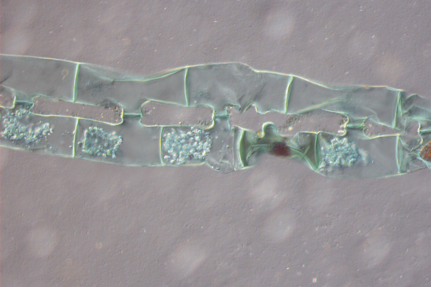
, Transdescantia (wildflower), and Micrasterias (green algae).")
 recorded with Wollaston prisms having different splitting angles.")
. With DIC users are able to visualize small height differences on the wafer surface more easily.")
 and oblique (right) brightfield illumination using a Leica compound microscope. The defect on the wafer surface is clearly more visible with oblique illumination.")
