
Targeting nuclear pore complexes (NPCs) using cryo confocal microscopy
Nuclear pore complexes (NPCs) are large protein assemblies which connect the outer and inner membrane of the nucleus of eukaryotic cells. NPCs are assembled from several hundred nucleoporins (NUPs) which form a central channel enabling selective nucleocytoplasmic transport of molecules: RNA and ribosomal proteins are transported from the nucleus, while nuclear proteins translated in the cytoplasm, signaling molecules, lipids, and others, are shuttled into the nucleus.
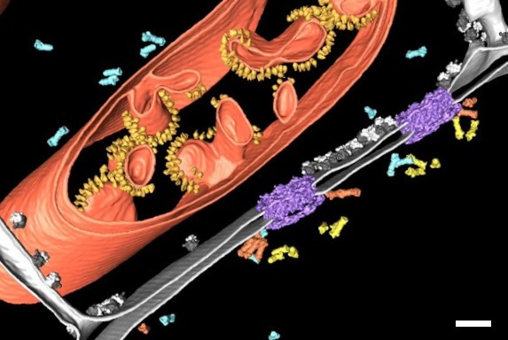
To better understand the structure-function relationship of NPCs and the regulation of their biogenesis and turnover, it is crucial to investigate their structure in the cellular context with the highest resolution. Figure 1 shows a segmentation of a cryo-electron tomogram of the nuclear envelope [2]. The tomogram revealed that proteasomes bind to NPCs “establishing a hub for protein degradation at the gateway between nucleus and cytoplasm” (Albert, S. et al., PNAS, December 2017). This clearly shows how cryo-electron tomography (cryo ET) provides insights about the cellular architecture and molecular sociology. But how can rare specific cellular events, e.g. NPCs undergoing autophagy, be selectively examined with cryo ET?
Cryo Electron Tomography
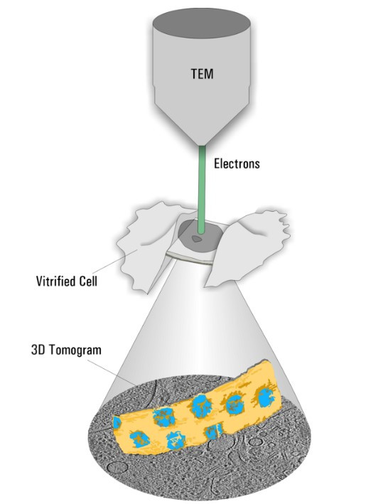
Cryo ET is a dedicated transmission electron microscopy technique where a series of tilt images is acquired and a 3D volume of the observed area is reconstructed (Figure 2). With the recent advances in EM hardware and software, resolutions down to the sub-nanometer range can be achieved. To maintain the sample as close as possible to the native state, it is plunge frozen quickly to avoid the formation of destructive ice crystals. The process resulting in such amorphous ice is called vitrification.
Cryo FIB Milling
Only specimens below 300 nm thickness can be directly assessed by cryo ET. Thicker samples, e.g. nuclei in yeast for NPC analysis, have to be thinned down by a milling process. Dedicated dual beam microscopes, encompassing a scanning electron microscope and focused Gallium ion beam (cryo FIB-SEM), are employed to ablate unwanted material (Figure 3).
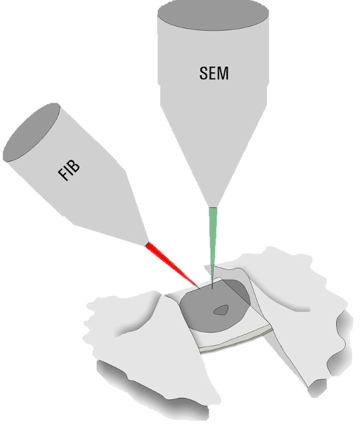
During the milling process, material above and below an area of interest is removed to produce a lamella of 200–300 nm thickness. By FIB milling, parts of thick cellular specimens which could not be examined are now accessible for cryo ET.
Cryo Light Microscopy
To obtain a tomogram of a specific cellular site like an NPC undergoing autophagy, it is essential to identify the structure-of-interest during FIB milling and cryo ET. As most structures are not clearly recognizable in the SEM prior to or during milling, a method for visualizing and targeting molecules of interest under cryogenic conditions is needed.
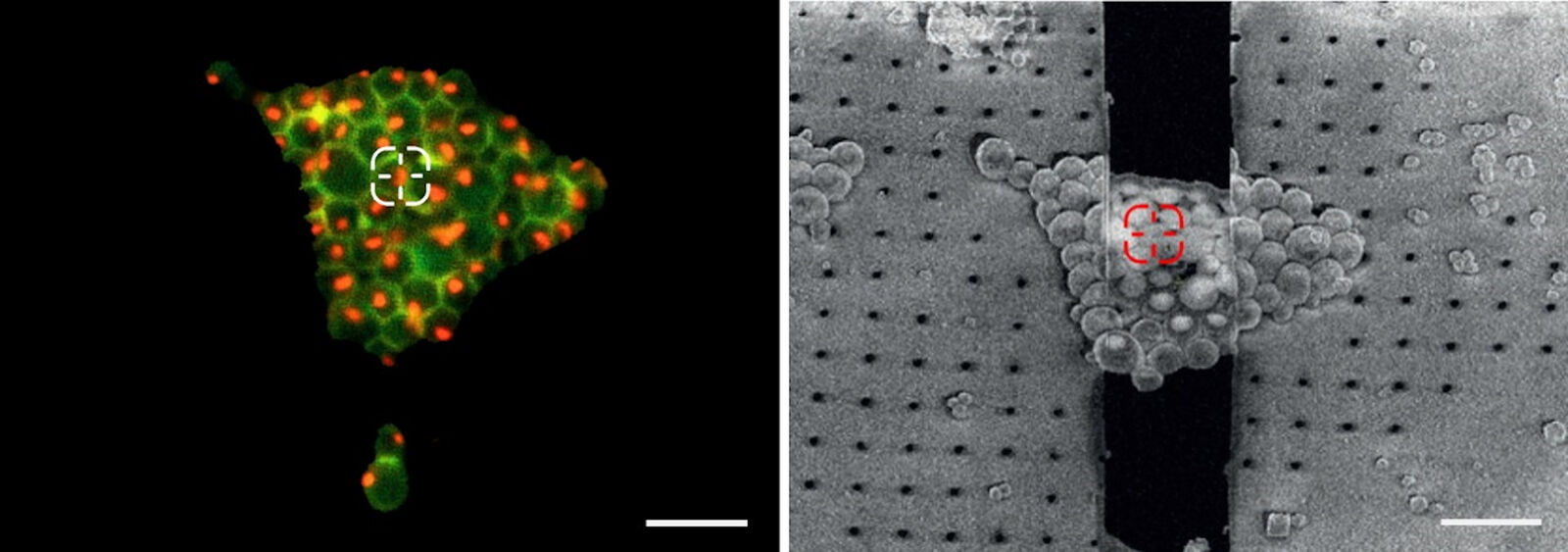
To resolve this issue, cryo fluorescent light microscopy is essential, e.g. with the THUNDER Imager EM Cryo CLEM. Using genetically encoded fluorescent markers, specific target sites in the cell can be visualized and structures of interest identified and marked. In turn, the images and xy coordinates can be retrieved in subsequent EM steps (Figure 4).
Of course, the microscope hardware has to maintain the sample vitrified at all times. Modern widefield microscope systems use very sensitive cameras that detect even faintly expressed proteins. In addition, inherent challenges of widefield systems, like out-of-focus blur, can be removed by applying the newest computational clearing technologies.
Nevertheless, it is not sufficient to only retrieve the xy coordinates of the structures of interest, but also the z coordinate is necessary in order to improve the likelihood that the target structure is contained within the resulting FIB lamella. Unfortunately, the resolution along the optical axis is limited in widefield microscopes.
To improve the z resolution, confocal microscopy is the next logical step. A pinhole placed at an intermediate focus plane blocks the out-of-focus light, hence increasing contrast and resolution, in particular along the z axis (for more information about the confocal principle).
3D targeting workflow using confocal microscopy
In the following, the workflow to identify fluorescent targets in cryo confocal microscopy in 3D and how to retrieve the fluorescent target in the cryo FIB-SEM, with the goal of retaining it within the final FIB lamella in a more reliable way for further investigation in the cryo TEM, is described.
1. Camera overview for checking the grid quality and target distribution
In order to evaluate the quality of the cryo EM grid and the sample, a camera overview image is created. Using transmission or reflection microscopy, the carbon foil and its integrity or defects can be made visible (Figure 5).
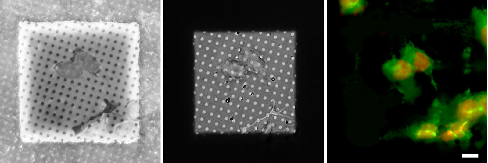
At the same time, information about the cells and their position in relation to the grid squares can be judged. Only targets near the center of the grid square can be assessed in the subsequent EM steps. To improve the positioning of cells, micropatterning techniques can be applied prior to the seeding of the cells on the foil [3].
In the following, the 3D cryo targeting process is explained in detail based on unpublished images (courtesy of Herman Fung and Julia Mahamid, EMBL, Heidelberg, Germany) and data contributing to the article In-cell architecture of the nuclear pore and snapshots of its turnover [1].
The information about the foil integrity together with the location of suitable targets within the grid square visualized by fluorescence allows the selection of suitable sites for FIB milling (Figure 6).
2. 3D information via a highly resolving confocal z stack
After selection of the relevant positions for FIB milling, a series of fluorescence images along the optical axis is created at these positions to obtain the 3D information. To improve the resolution in the z direction in comparison to standard widefield systems, confocal microscopy is the method of choice. By means of a laser, the sample is scanned point by point, while only the in-focus information of the fluorescence emission is recorded. The 2D images recorded at different z positions are then assembled into a 3D stack (Figure 7).
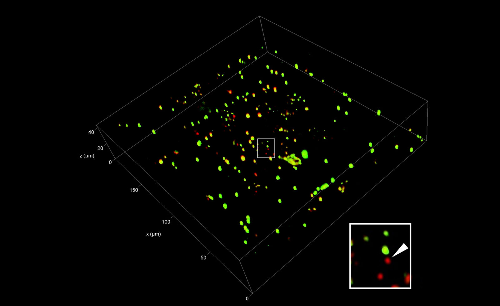
The axial resolution of microscope systems is mainly dependent on the opening angle of the objective used (the so-called numerical aperture). As commercially available cryo microscopes use air objectives for the convenience of the user (no immersion needed that may compromise maintaining the vitrified state of the samples), the actual resolution is limited. Typical resolutions of 200 nm in xy and about 800 nm in z can be achieved.
To enable proper targeting of a cellular site of interest, fiducial beads can be applied to the sample as reference structures for alignment and correlation between the fluorescence and EM images in 3D [4].
Typical beads are 1 µm in size and completely spherical which enables sub-diffraction fitting of their center coordinate. Microbeads that contain metals can be more clearly visualized via back-scattered electrons in the SEM, distinguishing them from similar size ice crystals. Beads are preferentially chosen, such that their fluorescence emission is different from that of the actual target, to enable better discrimination (Figure 8).
3. Marking fiducial beads and targets
As the fiducials are visible in both the LM and SEM, their coordinates can be used to transform parameters like rotation, translation, and scaling between both modalities. Target coordinates marked in the confocal microscope can then be transformed to the FIB milling process to increase the probability to obtain the structures of interest in the FIB lamella.
Unfortunately, commercial software solutions for precise 3D targeting are not yet developed, but an open source solution is available, based on the publication mentioned above (3D Correlation Toolbox).
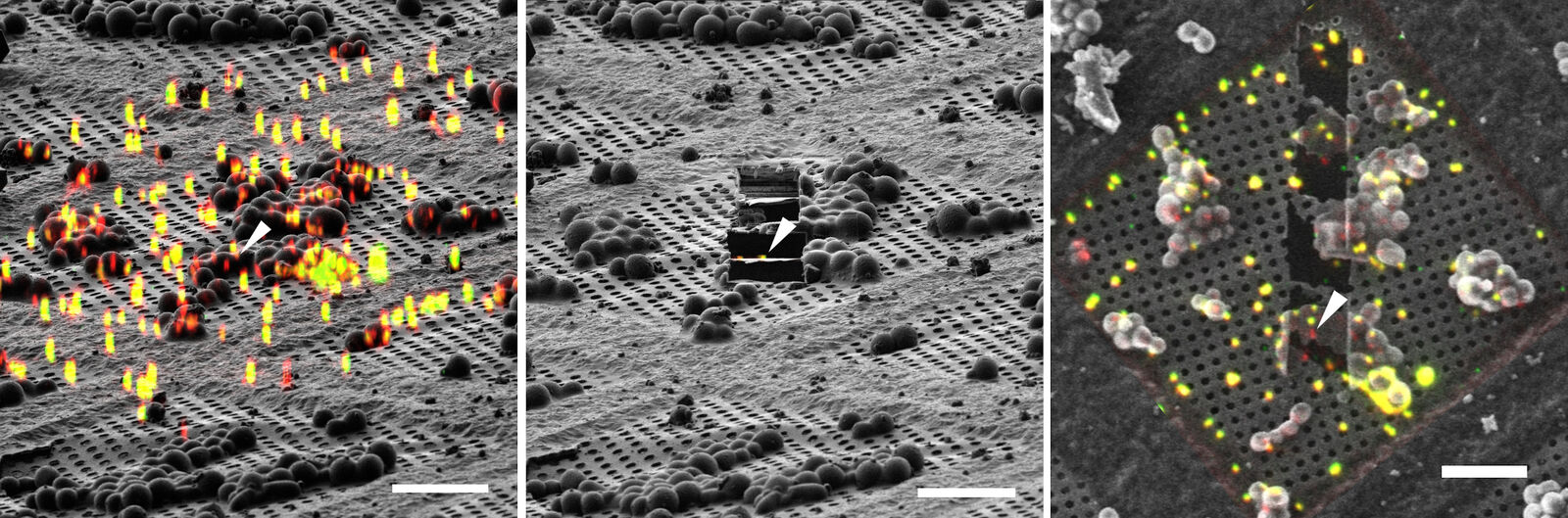
Using 3D Correlation Toolbox, the confocal image data can be loaded, targets and fiducial beads marked, and their center coordinates automatically determined. The defined coordinate markers are then projected onto the FIB image for definition of the xyz coordinates for milling (Figure 9).
4. FIB Milling
For milling of the target region(s) to a suitably thin volume, two milling windows are placed above and below the structure of interest, as visualized by the projection of fluorescence signal onto the FIB image (Figure 9). A Gallium ion beam is then applied and the material in the respective windows removed. Several lamellae can be created on one EM grid increasing the efficiency of the workflow.
5. Cryo Electron Tomography
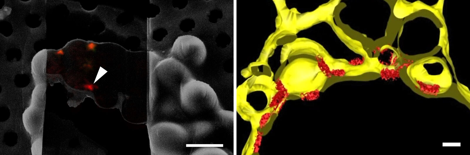
In order to obtain structural information of the sample at molecular resolution, the cryo lamella is imaged using a cryo transmission electron microscope. By registering between the SEM and TEM views of lamellae, areas for tilt-series acquisition can be defined based on the fluorescence signal of the target contained in the lamella. The imaged tilt series is then combined computationally to reconstruct a 3D volume of the interior of the cell. Better resolved structures of macromolecules can be achieved by averaging the structural information of many individual proteins of the same kind (sub-tomogram averaging). In Figure 10, the lower lamella shown in Figure 9 was imaged by cryo ET. The resulting segmentation of the tomogram shows the nuclear membrane with the targeted NUP positions.
Summary
In this article it was shown that cryo confocal microscopy is an essential component in cryo workflows to assess the quality and target distribution of vitrified samples on EM grids. The highly resolved confocal data recorded under cryo conditions allows scientists to locate structures of interest under fluorescence in 3D. The 3D volume serves as a reference for the correlative approach to retrieve the target structures in the FIB-SEM for milling and, subsequently, perform electron tomography in the cryo TEM to acquire a high-resolution representation of the target in its native cellular environment.
Acknowledgements
I would like to thank Dr. Julia Mahamid, Dr. Kar Ho Herman Fung for the images and the feedback on this article, and the whole Mahamid Group, in particular Dr. Xiaojie Zhang and Dr. Jenia Zagoriy, for constant support and fruitful discussions about cryo confocal applications.
 labeled with membrane-permeable calcein, high-pressure frozen in salt water using EM ICE.")


