 taken with a ring light (RL) and near vertical illumination (NVI).")
What type of microscope light source is best for inspection?
Up until 10 to 20 years ago, halogen lights [5] were the most common type of illumination for inspection microscopes. However, since that time LED (light-emitting diode) lights [6] have been more and more utilized for microscope illumination due to the reasons given below.
Advantages of LED (Light-Emitting Diode) illumination
LED microscope illumination technology provides several advantages for microscopy imaging when compared to halogen lights. These advantages are:
- Longer lifetimes (25,000 to 50,000 hours)
- Lower power consumption
- Natural color temperature
- Constant color temperature even at low brightness levels
- Less heat release (a “cold light” source useful for temperature-sensitive samples)
- A more practical and compact design
Why is microscope illumination important during inspection?
There are several key factors to consider for high quality microscopic observation and imaging of a component or part when selecting the proper type of illumination:
- Types of sample (components, parts, etc.) to be observed;
- Sample characteristics (shiny or transparent areas, holes, scratches, surface structures, etc.) to be analyzed;
- Difficulties noticed for specific applications (inspection, FA, R&D, etc.) with currently used types of illumination;
- Need to access samples during microscope observation, e.g., handling with tweezers, soldering iron, or other tools, which requires sufficient working distance [7] between the sample and objective with illumination.
Users of inspection microscopes may have to try multiple types of illumination in order to find the optimal lighting [7].
Choose the right LED microscope illumination
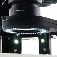
The LED illumination solutions are described below. These include the LED3000 and LED5000 systems, mainly used with stereo [8] or digital microscopes, which are often exploited for inspection. Examples of other applications they can be used for are failure analysis (FA) and research and development (R&D). Some basic information about the LED3000 and LED5000 systems are shown in table 1.
Overview of LED3000 and LED5000 microscope illumination solutions
Ring light (RL) gives bright and uniform illumination; suitable for many types of parts and components. Additionally, diffusors and polarized light sets are available for both ring-light types. These accessories reduce the problems of glare and highlighting of spots.
 gives bright and uniform illumination; suitable for many types of parts and components.")
Coaxial illumination (CXI), where the beam of light is guided through the optics and reflected from the part and component, works best for smooth and reflective components. It is especially useful if fine cracks or surface quality must be assessed.
, where the beam of light is guided through the optics and reflected from the part and component, works best for smooth and reflective components.")
Near vertical illumination (NVI) is achieved with LEDs positioned very close to the optical axis. It provides nearly shadow-free lighting and is practical for parts and components with recesses and deep holes or those that require long working distances.
 is achieved with LEDs positioned very close to the optical axis.")
Spotlight illumination (SLI) with flexible goosenecks offers high contrast lighting suitable for many types of parts and components.
 with flexible goosenecks offers high contrast lighting suitable for many types of parts and components.")
Diffuse and highly diffuse illumination (DI and HDI) are designed for reflective, non-flat or curved parts and components. These can be difficult to image due to the amount of back-reflected light.
 are designed for reflective, non-flat or curved parts and components.")
Multi-contrast illumination (MCI), utilizing repeatable contrast with lighting from 2 different directions and angles, is useful for parts and components with hard-to-find details.
, utilizing repeatable contrast with lighting from 2 different directions and angles, is useful for parts and components with hard-to-find details.")
Back light illumination (BLI) provides transmitted lighting for parts and components with transparent areas.
 provides transmitted lighting for parts and components with transparent areas.")
Results with Leica LED5000 and LED3000 illumination
Example images of various samples are shown below. The images were recorded with a Leica stereo microscope (M60 or M125) equipped with a Flexacam c5 digital microscope camera and a LED3000 or LED5000 illumination system. The types used were a ring light (RL) [with diffusor or polarizers], near vertical (NVI), coaxial (CXI), spotlight (SLI), multi-contrast (MCI), and diffuse (DI) or highly diffuse (HDI) illumination.
Reference Sample: Coin
Images of a metallic coin acquired with various LED illuminations are shown in figure 1. The coin images demonstrate clearly the differences in contrast which can be achieved.
, all segments")
, right half segments")
, upper left quarter segments")
")
")
")
")
, both lights")
Printed Circuit Board (PCB)
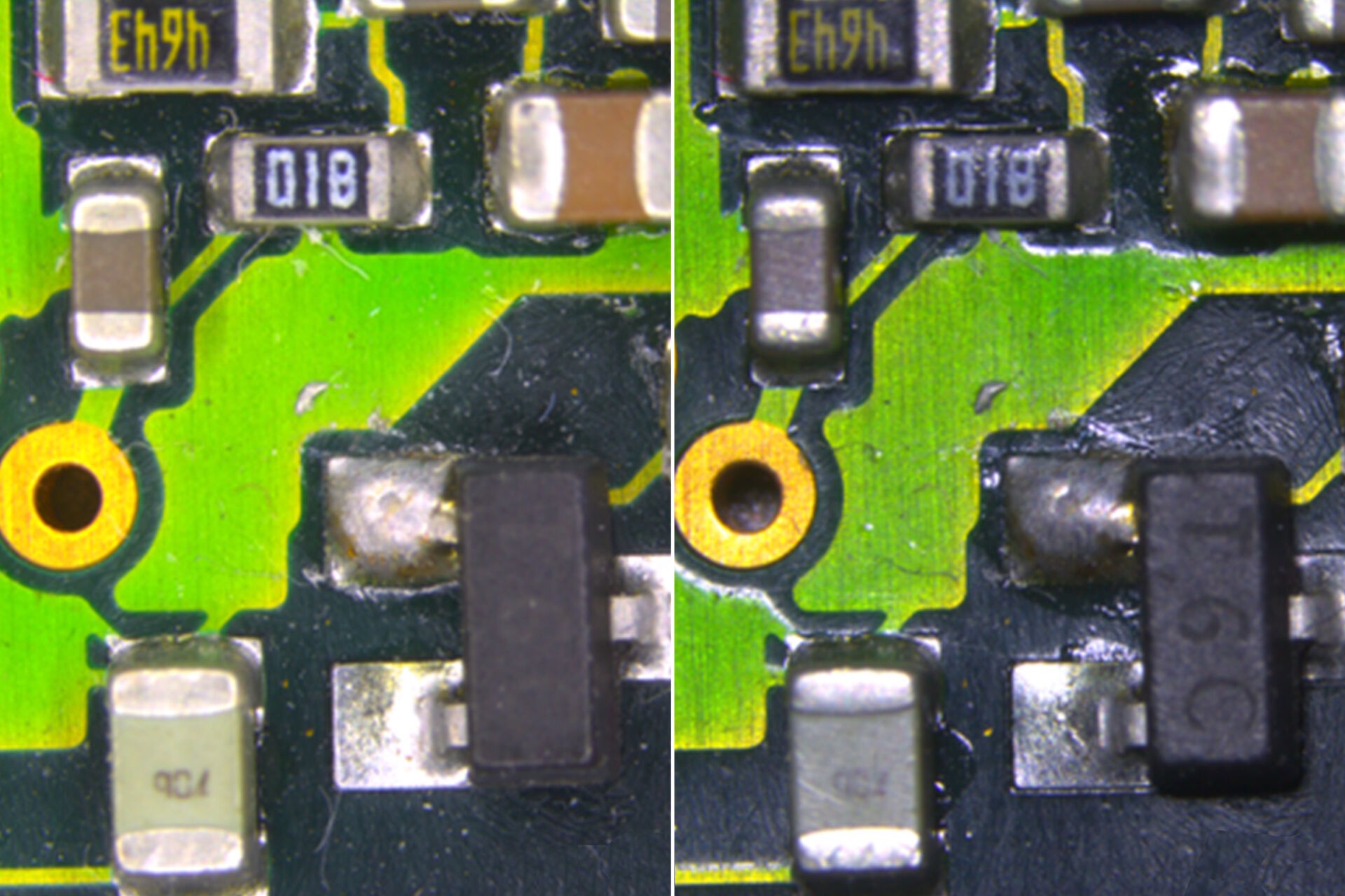
Images of a PCB recorded with a RL, NVI, and SLI illumination are shown in figure 2.
 - Ring Light (RL) with diffusor: Multiple sample characteristics")
 - Near Vertical Illumination (NVI): Holes and recesses")
 - RL with crossed polarizers: Reflective areas")
 - Spotlight Illumination (SLI): Multiple sample characteristics")
Processed wafer
Images of a processed wafer recorded with a RL, NVI, CXI, and SLI illumination are shown in figure 3.
 with diffusor: Multiple sample characteristics")
: Surface texture")
: Holes and recesses")
: Multiple sample characteristics")
Automotive component
Images of a sprocket recorded with a RL, NVI, and SLI illumination are shown in figure 4.
 with diffusor: Multiple sample characteristics")
: Holes and recesses")

: Multiple sample characteristics")
Medical Devices
Images of a hip implant recorded with a RL, NVI, or SLI illumination are shown in figure 5.
 with diffusor: Multiple sample characteristics")
: Holes and recesses")

: Multiple sample characteristics")
Guide for choosing the appropriate LED illumination
The quick selection guide for the LED3000 and LED5000 series of illumination solutions is shown below in table 2. The LED3000 series is designed for more routine applications (e.g., inspection and QC) and the LED5000 series for more advanced applications (e.g., FA and R&D). This guide can be very helpful for microscope users attempting to find the most appropriate illumination for inspection of particular components or parts.

Other recommendations
In addition to the high-quality optics integrated into Leica microscopes, it is important to identify the component details to be analyzed and the field of view (object field) required for observation when selecting an illumination system. It is also worthwhile to consider the advantages of computer encoding of the microscope and the performance of the microscope’s optics, such as objective lenses in terms of transmission, chromatic correction, and planarity, i.e., planapochromatic, achromatic, etc.
Conclusion
Finding the right microscope illumination for inspection of components or parts can be challenging at times. However, the advice and recommendations mentioned here can aid users when investigating various illumination solutions in order to find the ones which give optimal results for image observation and recording.

, Tropomyosin (cardiomyocytes, red) and GFP (primordial cardiac layer, green).")