.")
Introduction
Electron microscopes, including transmission electron microscopes (TEM) and scanning electron microscopes (SEM), are widely utilized to gain detailed structural information about biological samples or non-living materials. Ultramicrotomy is the preferred technique for producing ultrathin sections, less than 100 nm thick for TEM/SEM analysis. During sample preparation small sample pieces are embedded in epoxy or acrylic resin, excess resin is trimmed away, and the specimen is sliced into ultrathin sections (50 nm - 100 nm) using a glass or diamond knife.
To gain insight into the structural information in 3D, volume electron microscopy (vEM) is becoming popular. Unfortunately, when working with large specimens, it is often crucial to focus on a specific subvolume of interest to optimize acquisition time and data volume, thereby increasing the efficiency of the workflow. Morphological features can be used to find such a region of interest (ROI), but to specifically identify cells or structures, fluorescence is often the method of choice. Many dedicated molecular markers such as direct markers and genetically encoded fluorescence proteins are available and can be used to guide the ultramicrotomy and the EM image acquisition to finally allow correlative light and electron microscopy (CLEM) as well.
Leica Microsystems’ ultramicrotome UC Enuity can be equipped with a highly magnifying, motorized stereo fluorescence microscope. This configuration enables the visualization of fluorescence during trimming and sectioning, allowing fluorescence targeting during the ultramicrotomy steps.
Despite the fact that many CLEM workflows have been developed, using fluorescence to identify specific targets within a resin-embedded specimen remains challenging. In particular, as standard concentrations of heavy metals and epoxy resins required for volume SEM sample preparation can impair fluorescence, making them less suitable if not unsuitable for light microscopy. Standard concentrations of heavy metals and epoxy resins often required for vEM sample preparation can impair fluorescence, making such protocols less suitable or unsuitable for light microscopy in some cases.
To overcome this, protocols have been developed to preserve fluorescence during sample preparation, enabling an accurate localization of fluorescently tagged structures.
Sample Fixation
To prepare a specimen for electron microscopy (EM), the first task is the immobilization of the specimen.
In the protocols highlighted here, physical cryo-fixation was used as an alternative to the classical chemical fixation techniques. Here, a sample is almost instantaneously frozen under high pressure (high pressure freezing, HPF), preventing ice-crystal formation and keeping the water in a glass-like (vitrified) state. This is supposed to be a state as close-to-native as possible. For cell layers, cryofixation can be achieved using a plunge freezing device (e.g. Leica Microsystems’ EM GP2), but for pellets and thicker samples up to 200 µm in depth, HPF is performed (e.g. using the Leica EM ICE)[1].
Freeze Substitution and Contrasting
The sample is then dehydrated in a solvent at temperatures below or close to −90°C (freeze substitution, FS), allowing the preservation of the ultrastructure. FS is considered to allow a better preservation compared to chemical fixation. In general, for IRF acetone is preferred over ethanol for dehydration, but exposure is kept short to avoid fluorescence loss. As organic materials and embedding resins have low electron density, during FS heavy metal compounds like uranyl acetate (UA) and osmium tetroxide are added, which have specific affinities for proteins and lipids.
As osmium tetroxide impairs fluorescence, UA in low concentrations was used during freeze substitution in the protocols below.
Infiltration and Embedding
After the substitution of water, the solvent is used to dilute the resin, promoting infiltration of the sample prior to curing allow the infiltration with a resin. To preserve fluorescence and to avoid high curing temperatures acrylic resins like Lowicryl® HM20 or LR White are found to be optimal. Furthermore, acrylic resins can be applied at low temperatures (around -20°C) helping to maintain the structural integrity of the sample.
Exemplary Protocol 1 – Cellular Samples
Cryo Fixation
For HPF, cells are usually grown on sapphire discs (as glass would be destroyed) or applied as a suspension directly into the sample holder. Standard assembly and HPF protocols are available from the different manufacturers (e.g. Leica EM ICE)[1]. To prevent the formation of extracellular ice crystals and enhance the quality of freezing, cryoprotectants can be used. Non-penetrating liquids such as dextran (15-20%), Ficoll® (5-20%), or undiluted 1-hexadecene are typically applied during the assembly of the sample holder for high-pressure freezing.
Freeze Substitution and Contrasting
Freeze substitution is performed using a low concentration of 0.1% uranyl acetate in dry acetone, as mentioned above, some protocols even reduce down to 0.04% UA depending on the cell type and UA stocks sources. While some protocols recommend an initial incubation for 72 hours at −90°C, shorter durations can be used for cellular samples to expedite the lengthy process (Figure 1). To minimize manual interaction during extended protocols, an automatic freeze substitution system with liquid handling is beneficial. Leica has developed such a device, the Automatic Freeze Substitution System EM AFS2, equipped with a liquid handler, the Freeze Substitution Processor EM FSP.
As shown in Figure 1, cellular samples are kept in 0.1% uranyl acetate in dry acetone at -90°C for 9 hours. Afterwards the temperature is gradually increased to -45°C and maintained at this level for 5 hours to allow the UA to stain the sample (this is sample dependent). Following this, uranyl acetate is removed through three washing steps with acetone, completing the freeze substitution and contrasting.
Infiltration and Polymerization
Next, infiltration with increasing concentrations of Lowicryl® HM20 resin begins in 2-hour sequences while the temperature is raised to -25°C. The temperature is kept below -20°C to preserve the sample's integrity and to utilize the resin's low viscosity for effective infiltration, avoiding protein disruption. The temperature of -25°C is maintained during three cycles of resin exchange and throughout the subsequent major 48-hour block of UV polymerization. For this process, the liquid handler on the EM AFS2 is replaced by an automatic UV lamp. During the final 9-hour block, UV polymerization continues while the temperature is increased to a final 20°C, where the sample can be handled for subsequent trimming and sectioning (e.g. see this application note on fluorescence trimming)[2].

Exemplary Protocol 2 – Organoids and Embryos
Cryo Fixation
To cryo-fix samples like organoids, pieces of tissue or embryos of model organisms like Drosophila being larger than cells HPF is the method of choice, but the limitation is about 200 µm in thickness. Appropriate sample holders with varying volume are available, as unnecessary/non-sample space during HPF should be avoided. As the extracellular space is much larger compared to cells, the risk of destructive ice crystal formation is much higher. Hence, cryoprotectants are more frequently used.
Freeze Substitution and Contrasting
To maintain fluorescence, freeze substitution is performed with a low concentration of 0.1% uranyl acetate in dry acetone as well. Sometimes embryos or egg chambers are perforated to improve infiltration.
As one can see in Figure 2 the substitution phase is much longer than for cells, i.e. 72 h before the temperature is raised with a ratio of 3°C/h. Afterwards the samples spend another 5 hours at -45°C to ensure a proper staining. This is a crucial step for the contrasting and varies with the samples. Ronchi et al. describe this as optimal for their samples used (e.g. Drosophila ovaries and larvae, mammary gland organoids).

Infiltration and Polymerization
Subsequent to three washing rounds with dry acetone the Lowicryl® HM20 infiltration started with increasing concentrations during four 6 h blocks. During the third and fourth block temperature is raised to -25°C to further increase the infiltration rate. The temperature is kept below -20°C to preserve the sample's integrity and to utilize the resin's low viscosity for effective infiltration, avoiding protein disruption. The temperature of -25°C is maintained during three cycles of further infiltration with exchange and refill followed by a subsequent 48-hour block of UV polymerization. For this process, the liquid handler on the EM AFS2 is replaced by a UV lamp. During the final temperature raise to 20°C it is ensured that the resin fully hardens and stabilizes the specimen for the subsequent ultramicrotomy procedures (e.g. see this application note on fluorescence trimming)[2].
Example
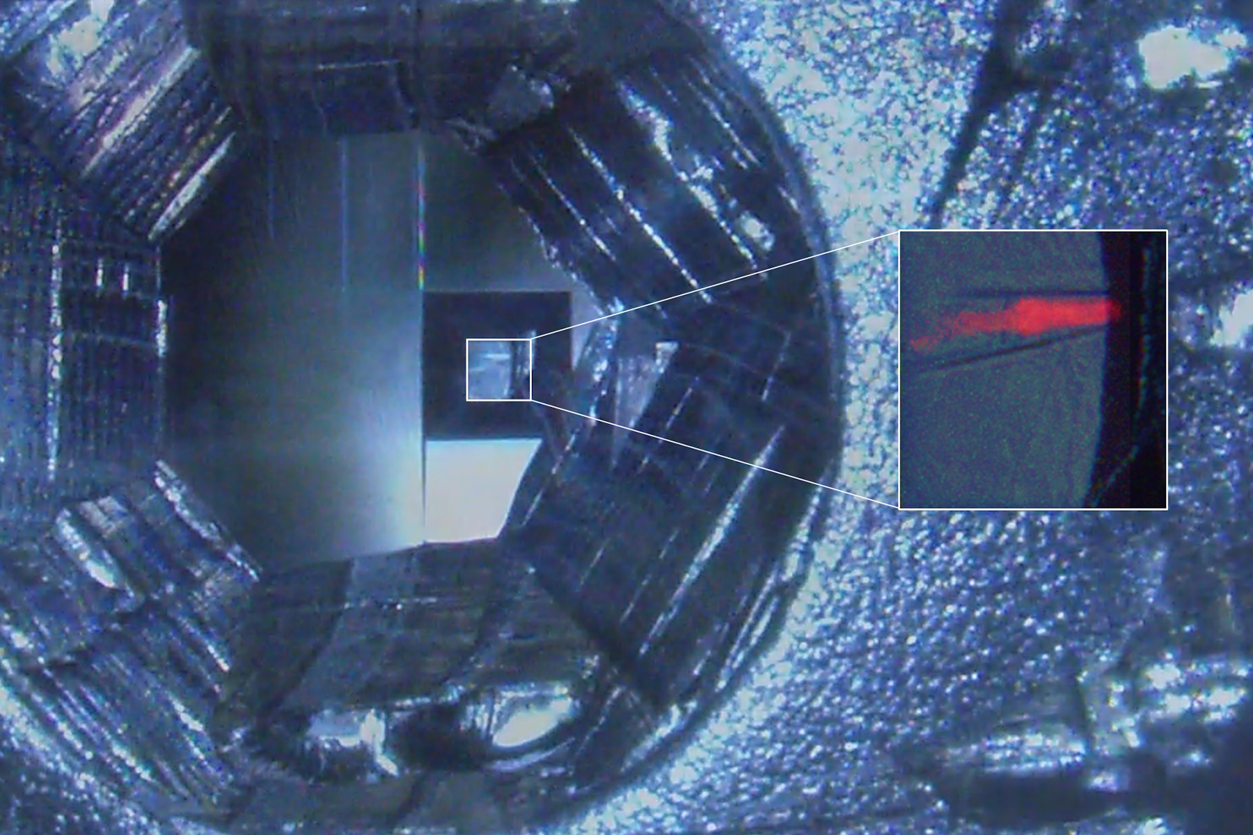
In order to use fluorescence for target trimming of a block face and to do post-embedding CLEM (not shown), the protocols described above were adapted to fit to C. elegans nematodes genetically expressing labels for the pharynx and the intestine (Figure 3). Flow-through chamber beems were manually pretrimmed. Afterwards the trimming areas to create a block face containing the target worm were configured and the trimming was performed automatically without user interaction on the UC Enuity. A detailed protocol of automatic trimming under fluorescence is shown here: Automatic Trimming with Fluorescence [2].

The adapted protocol is shown below (Figure 4).

Initial substitution time was 48 h followed by a 13 h temperature slope up to -45°. The blocks with increasing HM20 concentrations were 4h. These blocks were adjusted to be between the durations described in the protocols above. This is in line with experiences with the samples, their size, skin thickness and permeability.
Summary
In this article, we learned that fluorescence can be preserved during sample preparation for electron microscopy. Protocols were shown and the major steps explained. Key steps are high pressure freezing and freeze substitution with low concentrations of UA for electron contrast followed by embedding in acrylic resins.
This workflow enables researchers to use fluorescence during ultramicrotomy for targeted trimming and potentially target control during sectioning. Nevertheless, the efficient trimming of a subvolume guided by fluorescence alone already allows researchers to concentrate the EM data only on target areas, reducing beam time and overall costs.
IRF also allows post-embedding CLEM. This is particularly useful, as the shrinkage during sample preparation for the EM can be uneven, preventing a precise correlation between pre-embedding fluorescence and post-embedding EM data.
Acknowledgements
The author likes to thank Paolo Ronchi and Yannick Schwab (both EMBL Heidelberg, Germany) for allowing me to distribute their protocol also in the context of target trimming using fluorescence.
A special thank you also to Felix Gaedke, PhD (CECAD Cologne, Germany) for creating the samples and providing knowledge in many ways.
C. elegans kindly provided by Prof. Thorsten Hoppe, Inst. for Genetics, Cologne, Germany.
Original IRF protocols and further reading
- Nixon, S.J., Webb, R.I., Floetenmeyer, M., Schieber, N., Lo, H.P. and Parton, R.G. (2009), A Single Method for Cryofixation and Correlative Light, Electron Microscopy and Tomography of Zebrafish Embryos. Traffic, 10: 131-136.
- Wanda Kukulski, Martin Schorb, Sonja Welsch, Andrea Picco, Marko Kaksonen, John A.G. Briggs; Correlated fluorescence and 3D electron microscopy with high sensitivity and spatial precision. J Cell Biol 10 January 2011; 192 (1): 111–119.
- Christopher J. Peddie, Ken Blight, Emma Wilson, Charlotte Melia, Jo Marrison, Raffaella Carzaniga, Marie-Charlotte Domart, Peter O׳Toole, Banafshe Larijani, Lucy M. Collinson; Correlative and integrated light and electron microscopy of in-resin GFP fluorescence, used to localise diacylglycerol in mammalian cells. Ultramicroscopy, Volume 143, 2014, Pages 3-14, ISSN 0304-3991.
- Biel, S.S., K. Kawaschinski, K.-P.Wittern, U. Hintze, and R.Wepf. 2003. From tissue to cellular ultrastructure: closing the gap between micro- and nanostructural imaging. J. Microsc. 212:91–99.
, insulin SGs (orange), microtubules (red), nucleus (yellow), and plasma membrane (transparent).")

-b-poly(isoprene). Right: Poly(styrene)-b-poly(methyl methacrylate).")
