The penetration depth is determined by the incident angle and the wavelength of the laser light
The penetration depth of the evanescent wave is defined as the range where 37 % of the initial intensity at the interface of the declining evanescent wave are still available. It mainly depends on the incident angle of the laser light encountering the glass/water or glass/specimen interface (read more about the principles of TIRF microscopy). Accordingly, controlling the incident angle is essential to control the penetration depth of the evanescent wave. Tight, precise, reliable and reproducible control of the incident angle of the laser light is also mandatory for ensuring reproducibility of the achieved results. The incident angle of the laser light in turn depends on the radial distance of the laser spot in the backfocal plane of the objective, which is determined by the TIRF scanner.
The penetration depth of the evanescent wave is defined as the range where 37 % of the initial intensity at the interface of the declining evanescent wave are still available. It mainly depends on the incident angle of the laser light encountering the glass/water or glass/specimen interface (<link science-lab total-internal-reflection-fluorescence-tirf-microscopy-an-introduction>read more about the principles of TIRF microscopy). Accordingly, controlling the incident angle is essential to control the penetration depth of the evanescent wave. Tight, precise, reliable and reproducible control of the incident angle of the laser light is also mandatory for ensuring reproducibility of the achieved results. The incident angle of the laser light in turn depends on the radial distance of the laser spot in the backfocal plane of the objective, which is determined by the TIRF scanner.
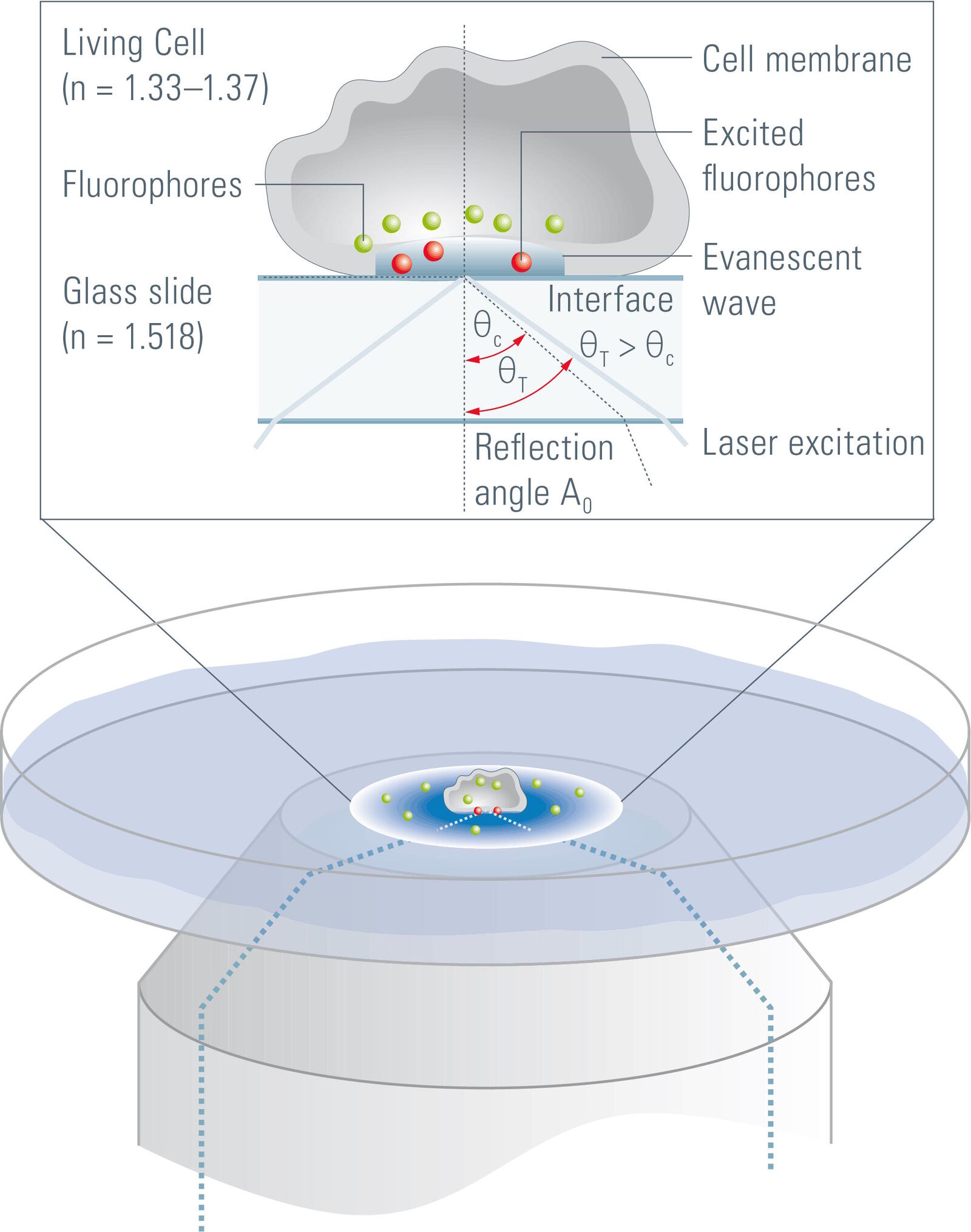
Another factor determining the penetration depth of the evanescent field is the wavelength of the laser light necessary for excitation. This can become a problem in TIRF experiments where multiple fluorophores are employed. In such experiments switching between the different laser lines would result in different penetration depths of the evanescent wave. The interpretation of the results from such experiments has to be undertaken very carefully, as the volume of the specimen penetrated by the evanescent wave and hence the number of fluorophores that is excited varies with the excitation wavelength. To achieve reliable and quantifiable results it is mandatory to keep the penetration depth of the evanescent wave at a constant value. This can only be achieved if the different penetration depths of the evanescent wave produced by the laser lines are compensated by changing the incident angle of the selected laser line accordingly.
Full control of the penetration depth with Leica TIRF auto-alignment
To ensure reproducible and reliable penetration depths of the evanescent wave even when the excitation wavelength is changed, Leica Microsystem employs special hardware for a fully automated TIRF alignment procedure. The main parts of the Leica TIRF module are a TIRF scanner, a collimator and the TIRF sensor. The TIRF scanner controls the position where the laser beam is placed in the backfocal plane of the objective. Hence, it controls the incident angle of the laser light at the specimen. The collimator focuses the laser beam in the rear objective plane (backfocal plane) to achieve a uniform illumination of the field of view. The TIRF sensor detects the light reflected from the glass/specimen or glass/water interphase in the situation of total internal reflection.
This makes the TIRF sensor a special part of the system, as it allows the occurrence of total internal reflection to be detected. The experimenter can therefore be 100 % sure that the images that are acquired are real TIRF images. In the fully automated alignment procedure, the TIRF scanner moves the laser beam through the backfocal plane of the objective and the TIRF sensor detects a range of scanner positions at which total internal reflection occurs. With this information the system then calculates – taking into account the wavelength of the laser beam – the penetration depth of the resulting evanescent wave for all possible scanner positions.
After the alignment it is possible to switch between laser lines while keeping a constant penetration depth of the evanescent wave, as the scanner will automatically change the position of the laser beam in the backfocal plane of the objective. This assures that the laser always has the desired incident angle to produce the demanded penetration depth of the evanescent field with respect to the wavelength of the laser light. The results are freely definable, but nevertheless stable and fully reproducible penetration depths of the evanescent wave for all available wavelengths.
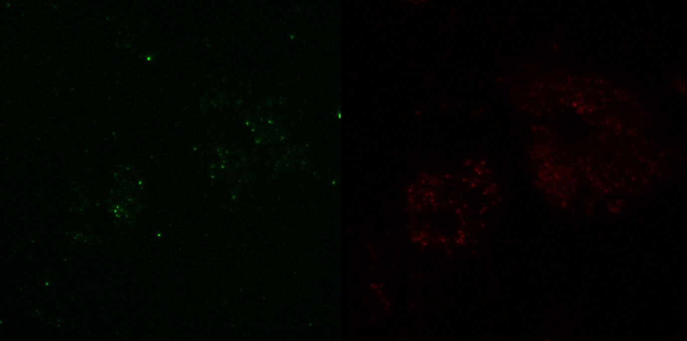
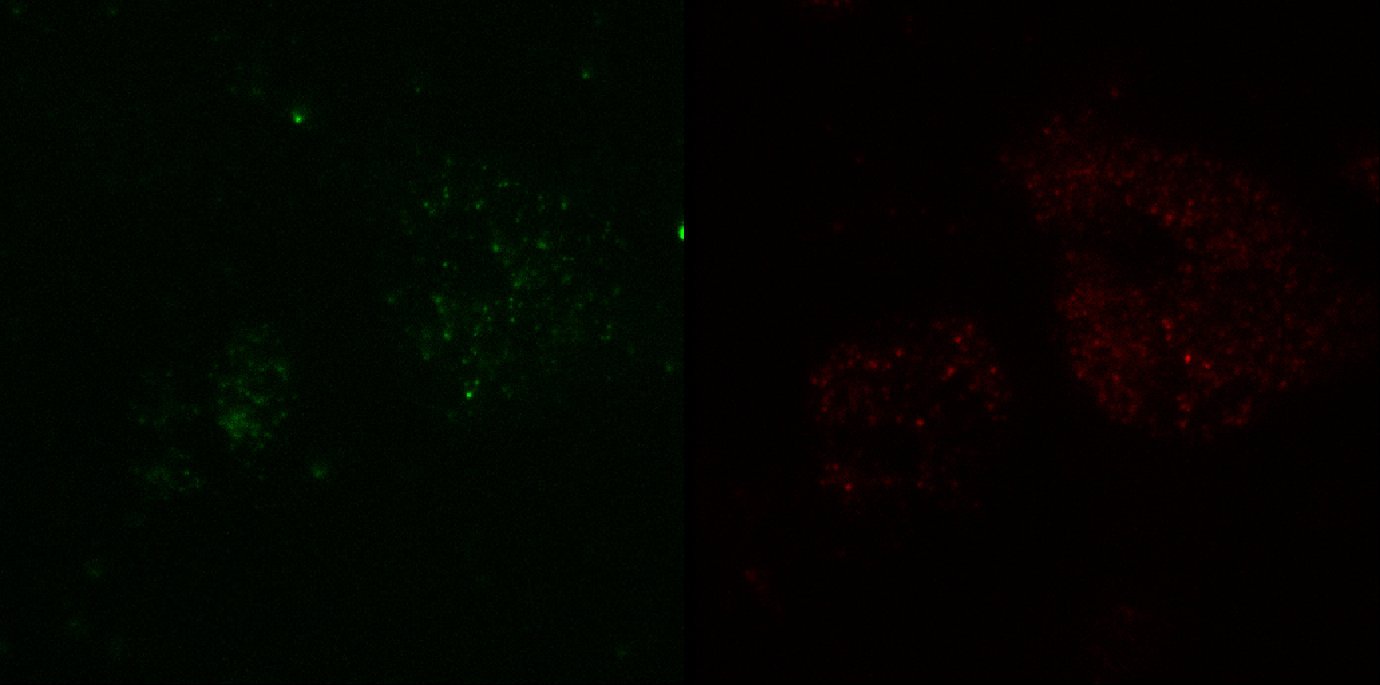
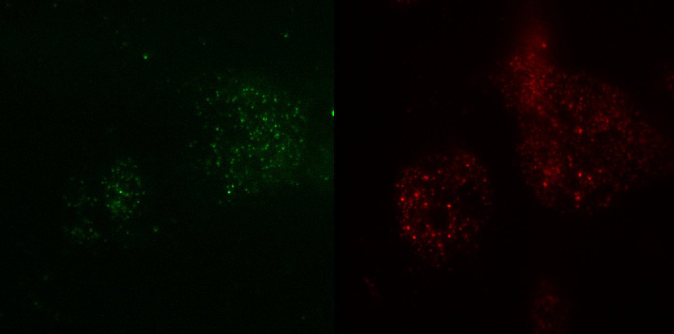
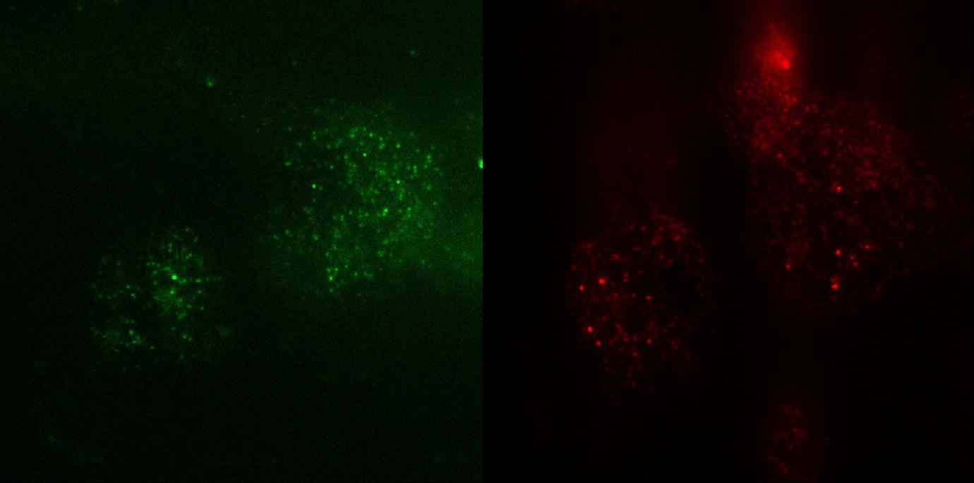
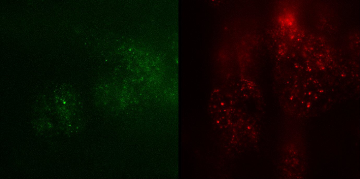
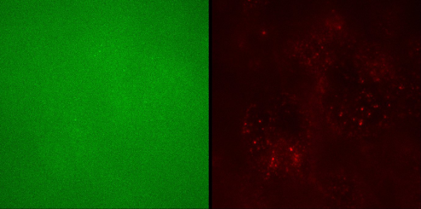
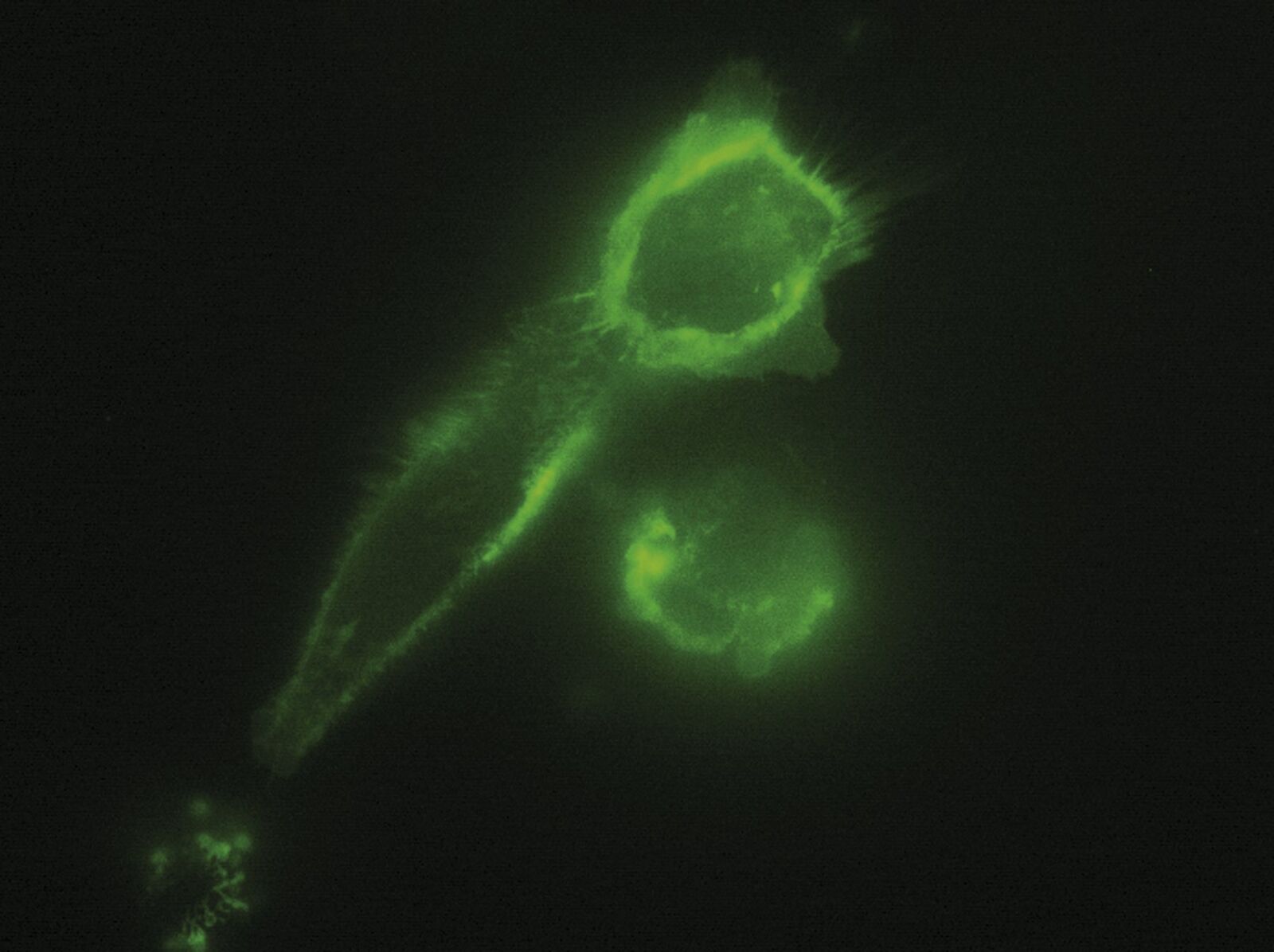
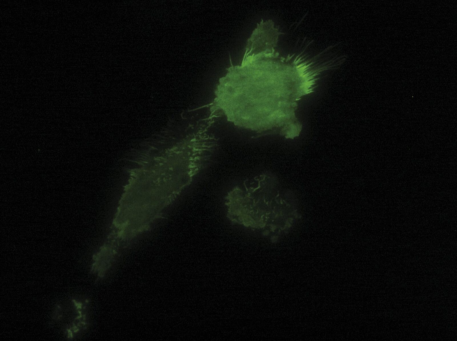
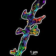
Fig. 3: TIRF images of fluorescently labelled Rab11 (green) and Gal3 (red) protein in vesicles of the apical membrane of MDCK cells. The images were acquired with different penetration depth settings. Top left: 90 nm, top right: 110 nm, center left: 150 nm, center right: 200 nm, bottom left: 250 nm, and bottom right: Epi mode. Note the increasing number of visible vesicles and decrease of the signal-to-noise ratio. Images acquired with a Leica AM TIRF MC system. Courtesy of Dr. Sophie Veitinger, Institute of Cytobiology and Cytopathology, Philipps University Marburg, Germany.
A flexible TIRF scanner enables HILO imaging and azimuth selection
Employing a highly flexible TIRF scanner has additional advantages. As mentioned, the system exactly recognizes at which laser positions (or scanner positions) total internal reflection occurs and, vice versa, where this is not the case. The knowledge of exactly where total internal reflection occurs and where not can be used to illuminate the sample in a special so-called HILO mode. If the laser encounters the glass/water interface at an angle lower than the critical angle necessary for total internal reflection, the laser beam will pass through the specimen obliquely. Consequently, only parts of the specimen are encountered by the laser beam and only the fluorophores in this volume are excited. This results in images with low background and a very good signal-to-noise ratio compared to conventional epifluorescence images. An additional benefit of this method is that bleaching and phototoxicity are greatly reduced, which prolongs cell viability, especially in long-term experiments. The HILO mode is particularly suitable for quantitative studies of dynamic movement, the distribution or interaction of molecules and single molecule tracking. A standard application is vesicle tracking.
Another advantage of a TIRF scanner with freely definable in coupling positions is that the direction (the so-called azimuth) from which the laser light encounters the glass/water interface can be chosen. This means that the direction of the wavefront of the evanescent wave can be selected. This, in turn, has an impact on the direction of the propagation of the evanescent wave (horizontal or vertical in respect to the glass/water interface). The propagation direction in turn can influence the efficiency of fluorophore excitation, as they are usually dipoles which have a certain orientation. In the Leica TIRF system it is possible to select between four azimuth positions to ensure optimal excitation of the fluorophore.
An acousto-optic tunable filter (AOTF) and a multimode laser fiber guarantee ultrafast wavelength switching and a homogenously illuminated TIRF field
The benefits of the Leica TIRF auto-alignment are most obvious for multicolor TIRF microscopy in time-lapse applications. For this purpose, fast switching between the different laser lines is mandatory. This is achieved by employing an AOTF for selecting the desired laser line instead of a filter system. AOTFs are capable of switching between wavelengths within microseconds in a vibration-less manner and with reduced transmission loss compared to filter-based systems. An AOTF also allows tuning of the intensity of the laser beam passing through. Additionally, shutters become obsolete if an AOTF is employed, which also speeds up the switching between laser lines.
Another factor for best-possible TIRF microscopy is a homogenously illuminated field of view. For laser-based TIRF microscopy this is strongly dependent on the particular laser fiber used in the system. The best homogeneity can be achieved by employing a multimode laser fiber with an extremely high numerical aperture like the one used in the Leica TIRF system.
Related Articles
-
Live-Cell Imaging Techniques
The understanding of complex and/or fast cellular dynamics is an important step for exploring…
Jan 10, 2022Read article -
Microscopy in Virology
The coronavirus SARS-CoV-2, causing the Covid-19 disease effects our world in all aspects. Research…
Jul 13, 2020Read article -
Universal PAINT – Dynamic Super-Resolution Microscopy
Super-resolution microscopy techniques have revolutionized biology for the last ten years. With…
Mar 02, 2015Read article
