
Glass is one of the oldest materials known. Today, it is used for many applications, e.g., optical instruments, windows, doors, solar panels, containers for food, beverages, and medicine, so strict standards for glass quality must be met, especially for optics. Quality control of flat, hollow, and pressed glass with polarization microscopy is fast and cost-effective. Defects, like knot, metallic, and crystalline inclusions and bubbles, can be analyzed without time-consuming sample preparation.
Crystalline defects
Though silicate glasses can differ greatly in composition and properties, possible defects found in them are similar in type and arise from the same causes [1]. In addition to gaseous inclusions (bubbles), crystalline defects are common in everyday production. Quick glass-defect identification is critical so that appropriate measures can be taken during production.
Types of crystalline glass defects according to their origin:
- Melt-resistant contaminants of the raw materials and old recycled glass;
- Non-melted raw material components;
- Corrosion residue of fireproof mineral materials from the smelter; and
- Devitrification products.
Quick and reliable defect diagnosis
Distinction between crystalline inclusions, gas bubbles, and processing defects is achieved using either automatic inspection and sorting systems or manual sorting after visual inspection. Segments cut out using a glass cutter or diamond saw usually can be inspected microscopically without further processing. For large, opaque "stones", the defect is ground and diagnostics are carried out with incident light. Smaller inclusions in glass knots often cannot be brought into sharp focus due to the lens effect of the glass bead. Therefore, the knot is covered with an immersion solution that has the refractive index of the glass (Figure 1). Furthermore, the microscope setup presented here also permits quantitative polarized optical measurements; however, this requires flat polished sections of a defined thickness [2-4].
For non-destructive diagnostics of defects located several millimeters under the glass surface done at high magnification, it is recommended to use objectives with extra-large working distances. A 40x polarization objective with coverslip correction can be used, in addition to a 10x polarization objective, for quantitative measurements made on thin samples and for conoscopic examinations.
For brightfield transmitted light , the shape, color and relative refractive index of the surrounding glass can be determined by relief of the inclusion. Decentering the condenser or introducing variable opening shutters allows oblique illumination for contrast enhancement. Oblique illumination creates strong relief streaks that are virtually invisible with optimal Köhler illumination.
With transmitted light polarization contrast, isotropic, and anisotropic materials can be differentiated. For idiomorphic crystals, the extinction position can be determined and the order of the birefringence can be estimated using the lambda plate. Brightfield and incident light polarization contrast with incident light are suitable only for defects on the glass surface or for ground specimens. Oblique incident illumination, combined with transmitted light, allows surface details and colors of the inclusions to be identified.
.")
Fig. 1: Elimination of the lens effect when observing a glass knot with an optical microscope by immersing it in a fluid contained in a glued-on section of pipe (illustration based on the example in reference 2, image 3.63).
Examples of crystalline inclusions
Tin oxide (SnO2)
The heating electrodes for some smelters are composed of melt-resistant tin oxide. In the case of overloads, electrode material can flake off, resulting in the typical aggregates of blue, xenomorphic grains (primary tin oxide). At higher temperatures, these dissolve after a little while, forming what is known as a knot. At lower temperatures, long prismatic tin- oxide crystals (secondary tin oxide) can grow as thin needles (Figure 2) or felt-like aggregates (Figure 3).

Fig. 2: Blue granular tin oxide which remaines next to needle-shaped recrystallisation products. This is an example of a glass inclusion with strong photoelasticity in the surrounding glass. Image was acquired with transmitted light and polarisation contrast using a HC PL Fluotar 10x Pol objective. The image width is 1 mm.

Fig. 3: Felt-like aggregate of recrystallized tin oxide is seen here. Another example of a glass inclusion with strong photoelasticity in the surrounding glass. Image was acquired with transmitted light, polarisation contrast, a lambda plate, and oblique incident illumination using a HC PL Fluotar 10x Pol objective. The image width is 1 mm.
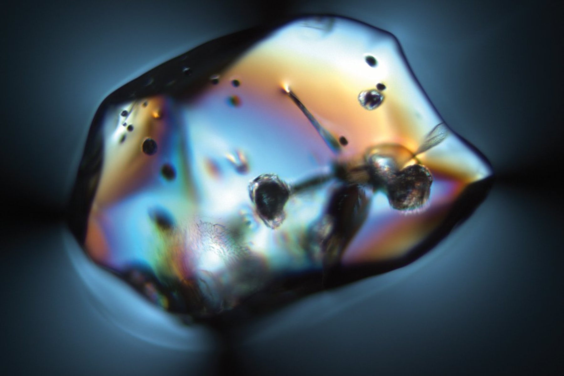
Zirconium oxide (ZrO2) and corundum (Al2O3, aluminum oxide)
Zirconium oxide and corundum are components of the fireproof minerals used in smelters (Figure 4). Under normal loads, the resistant zirconium oxide dissolves in a slow, "well-tempered" manner. Large amounts of zirconium-oxide glass defects indicate strong local corrosion, such as that due to thermal overload or excessive flow. Zirconium oxide occurs in its original compound as small white inclusions or forms typical dendritic crystals (Figure 5). Corundum, i.e., crystalline aluminum oxide (Al2O3) with traces of metals, is more easily dissolved in the glass smelter and usually forms glass knots and streaks. However, corundum can also take the form of rounded grains having other typical inclusions (Figure 6).
 and zirconium oxide (white egg-shaped inclusions).")
Fig. 4: A high-temperature-resistant fireproof mineral composed of corundum (light gray bar-shaped inclusions) and zirconium oxide (white egg-shaped inclusions). Image of this polished sample acquired with incident light and a HC PL Fluotar 10x Pol objective. The image width is 1 mm.

Fig. 5: Recrystallized zirconium oxide typically becomes crystal aggregates in a knot. Again here is an example of a glass inclusion with high photoelasticity in the surrounding glass. Images acquired with transmitted light, polarisation contrast, a HC PL Fluotar 5x objective, and A) a lambda plate or B) oblique incident illumination. The image width is 2 mm.

Fig. 6: Primary corundum which has numerous inclusions. Yet another example of a glass inclusion with strong photoelasticity in the surrounding glass. Image acquired with transmitted light, polarisation contrast, and a HC PL Fluotar 10x Pol objective. The image width is 1 mm.
Tridymite/cristobalite (SiO2)
Tridymite and, less frequently, cristobalite forms as devitrification products in SiO2-enriched glass. An example is when volatile components, such as alkalis or boroxide, evaporate. Typically, tridymite forms crystal aggregates with 60° angles (Figure 7).

Fig. 7: Tridymite dendrites are seen here in their typical formation as glass inclusions. Image was acquired with transmitted light, brightfield contrast, and oblique illumination for contrast enhancement using a HC PL Fluotar 10x Pol objective. The image width is 1 mm.