
From Anton van Leeuwenhoek to compound microscopes
Since the invention of glass by the Romans in the first century, people discovered that a magnification effect was created by round-shaped pearls of glass. Later on this effect was scientifically investigated and further developed, resulting in the simple magnification glasses of the 16th and 17th centuries, e.g., those invented by Hans and Zacharias Jansen or Anton van Leeuwenhoek. Historically, the birth of microscopy occurred at the same time [2].
By definition, the “microscope” is an instrument that magnifies objects that are not normally resolvable by the human eye [2,3], so these single lens tools were already microscopes (refer to Figure 1 Top). Nowadays, people think of something different when they talk about a microscope. This change is due to the fact that people soon realized that the combination of two separate lenses (or lens systems) in a row is a more effective visual tool than a single lens.

Fig. 1: Microscopy started with simple magnifying devices in the 16th and 17th centuries has been evolving ever since. Top) For an early microscope, the objective lens is a single lens magnifying a specimen. Middle) A compound microscope with finite optics consists of a two lens system. The objective magnifies the specimen and the eyepiece magnifies the image produced by the objective. The distance between the objective and ocular shoulder is called the mechanical tube length. Bottom) A compound microscope with Infinity Optics has an additional tube lens (TL).
To describe such a set-up the term “compound microscope” was created. Compound microscopes consist of an objective magnifying the specimen or sample and an eyepiece (more often two) magnifying the image produced by the objective (refer to Figure 1 Middle).
Introduction of infinity optics
The distance between the objective ocular shoulder is called the mechanical tube length (refer to Figure 1 Middle). As a standard, this value was set to 160 mm by the Royal Microscopical Society in the 19th century [4]. Over the years this design turned out to have some drawbacks. Adding additional optical elements into the light path, such as prisms for differential interference contrast (DIC), polarizers, etc., changed the effective tube length and introduced aberrations. These aberrations are corrected with the addition of other hardware components.
For this reason, in the 1930’s the microscope manufacturer Reichert started to experiment with so called infinite optics and this technology was later adopted by all other microscope companies. Objectives of these infinite optical systems project a specimen image to infinity, meaning that all light rays coming from a single point of the specimen which are non-parallel enter the objective and then exit it in parallel. Rays from the center of the field of view (imaged area) of the specimen (and the objective) run parallel to the optical axis. Those from outside the field-of-view center of the specimen run parallel to each other, but not to the optical axis.
The virtual image produced by an infinity-corrected objective has to be captured by an additional lens – the tube lens (TL) – which results in a real image at the front focal point of the eyepiece lens (refer to Figure 1 Bottom). This approach enables the addition of optical instruments, such as DIC prisms, into the “Infinity Space” between the objective and TL without influencing image quality. Neither the location nor the focal point of the image is altered.
Refer to Figure 2, top: A finite optical system consists of an objective and an eyepiece. The object is placed between the single and double focal point of the objective. The intermediate image produced by the objective is focused between the front focal point of the eyepiece and the eyepiece. Users can view the image through the eyepiece. Bottom: In an infinity-corrected system the specimen is placed in the focal point of the objective. In this case all rays coming from one point of the specimen are parallel after the objective, like an object placed in infinity. Rays coming from the specimen’s center will leave the objective parallel to the optical axis (not shown). Rays coming from a single point of the specimen’s periphery will leave the objective parallel to each other but not to the optical axis. The space between the objective and tube lens is called Infinity Space. Flat optical devices brought into this space will hardly affect the image since all rays coming from a single point of the specimen will experience the same optical influence. The tube lens forms a virtual image, which can be viewed through the eyepiece.
 A finite optical system. Bottom) Infinity-corrected system.")
Advantages of infinity optics
Several contrast methods require the introduction of special optical components into the microscope’s light path. For example, prisms and polarizers for DIC or dichroics and filters for fluorescence microscopy [5-7]. Introducing such optical components between the objective and the eyepiece of a microscope with finite optics alters the effective tube length and introduces spherical aberrations. These aberrations can be corrected with the introduction of additional optical elements, but at the expense of diminished light intensities or increased magnification.
In comparison, a microscope with infinity-corrected optics can have extra equipment installed into the infinity space for contrast methods without causing optical aberration. Devices installed in the infinite light path alter neither imaging scale nor location of the intermediate image. This advantage is due to the fact that all light rays coming from a single point of the specimen will leave the objective in parallel.
Overall image quality is not the only benefit from infinity optics. Since the magnification doesn’t change when placing different optical devices into the infinite light path, one can easily compare the exact same sample using different contrast methods. For example, specimens can be imaged in DIC and fluorescence simultaneously (refer to Figure 3).
 and fluorescence images (middle) can be acquired simultaneously (right).")
Fig. 3: Optical devices, such as DIC prisms or fluorescence filters, placed into the light path of finite optics reduce image quality. Introduced aberrations have to be fixed with the use of additional optical components which increase magnification. Optical components introduced into the infinity space don’t have an influence on magnification. So DIC images (left) and fluorescence images (middle) can be acquired simultaneously (right).
With a few exceptions, most microscopes have a revolver where different objectives can be installed and changed to obtain the desired magnification. Parfocality allows users to switch between objectives without needing to refocus on the specimen area imaged. With infinity optics, parfocality can be maintained even if additional optical instruments are added into the infinity space.
How to get even more devices into the infinite light path
Optical microscopy is always evolving. Development of new techniques requires access to the microscope’s light path. Examples include installing additional light sources or laser devices. For instance, fluorescence recovery after photobleaching (FRAP) [8] needs a laser to bleach fluorophores (refer to Figure 4). Another example is digital mirror devices (DMDs) which are used for optogenetics, uncaging, photoactivation, and photobleaching.

Fig 4: Some microscopy techniques demand the simultaneous coupling of additional light sources or lasers. For example, bleaching during FRAP experiments is done using a laser coupled into the infinite light path.
The introduction of Infinity Optics paved the way for these methods, because it simplifies the coupling of the necessary components into the infinity space of a microscope’s light path.
New approaches have been invented to get additional devices into the infinite light path. Technically, there are two ways to enter the infinity space: Either via the imaging path between the objective and TL or in the illumination path between the objective and light source (refer to Figure 5). Access through the imaging path has the advantage that dedicated modules, e.g., motorized fast filter wheels and shutters, can be installed easily on the microscope.
Nevertheless, one should keep in mind that the infinity space, although its name would suggest otherwise, cannot be extended endlessly by stacking modules in the microscope. The reason is that only light rays coming from the center of the specimen area being imaged are parallel to the optical axis.
Off-center light rays coming from one point of the specimen are parallel to each other, but will strike the TL at a certain angle. Of course, enlarging the imaging path between the objective and TL will result in a loss of light. More precisely, it induces vignetting and will reduce the field of view.
 between the objective and the tube lens (TL) or in the illumination path (bottom) between the light source (L) and the objective.")
Fig. 5: Access to the infinite light path of the microscope can be achieved either in the imaging path (top) between the objective and the tube lens (TL) or in the illumination path (bottom) between the light source (L) and the objective. The former approach requires stacking of the relevant module into the microscope which elongates the imaging path. The second approach allows users to utilize the microscope for multiple applications by installing mirrors and beam splitters in the illumination path.
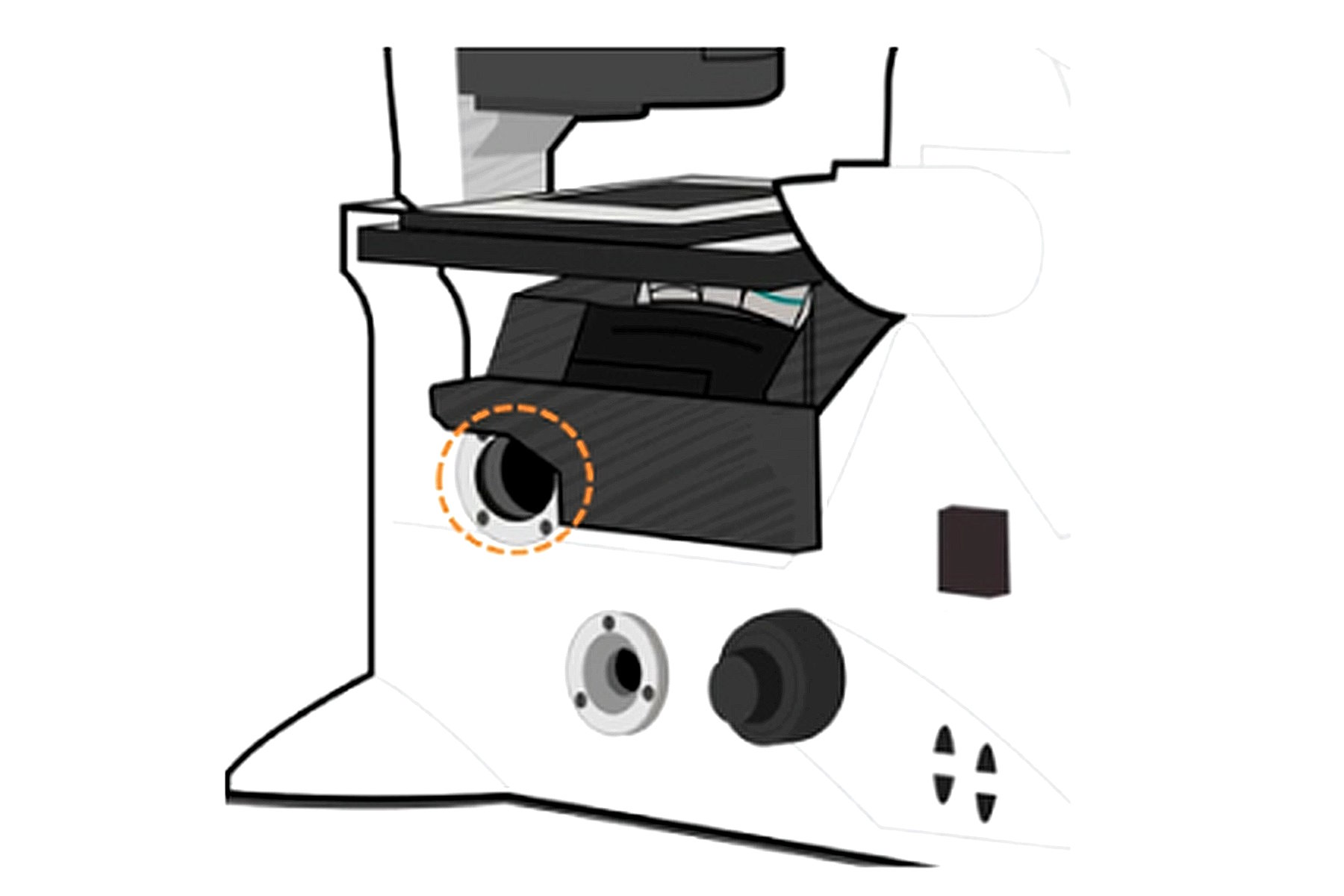
The Leica Infinity Port

Fig. 6: Stacking methods elongate the infinite light path of a microscope. However, a loss of light rays, which do not come from the center of the imaged specimen area, can result. The Leica Infinity Port neither elongates the imaging light path nor requires additional components in it, meaning it offers an significant advantage over stacking methods.
Entering the infinity space through the illumination path, such as the Infinity Port of Leica microscopes, circumvents the issue of having to elongate the imaging light path (refer to Figure 6). Besides preserving image quality, this feature has the advantage of being more universal. With the correct adapter at hand, any device can be attached to the microscope. In particular, microscope developers can build and connect their own devices, as well as 3rd party and Leica instruments, to create a customized imaging solution.
Video: The Leica DMi8 Infinity Port
Summary
The introduction of infinity-corrected optics considerably improved the functionality of the modern microscope. It made the necessity to correct aberrations introduced by prisms or other optical instruments required for contrast methods a thing of the past. Besides improved ease-of-use, infinity optics allow the simultaneous coupling of multiple light sources into the microscope.
The Infinity Port enables direct access to the infinite light path of a Leica microscope stand, circumventing problems that are created by stacking methods. This capability opens the door for researchers to easily install additional optical devices without sacrificing image quality and keep up with the latest microscopy trends.