
Magneto optical Kerr Effect
In the 1870s, scientist John Kerr discovered a magneto optical effect which eventually came to be named after him: the magnetic optical Kerr effect [1-3]. He observed that the polarization plane of linearly polarized light rotated after reflection from the surface of an iron magnet. The intensity of the effect depends on the magnetic domain dipole component which is parallel to the reflected light beam. Magnetic domains oriented parallel to the plane of the surface require oblique incident light. Known as the longitudinal Kerr effect (refer to figure 1A), a maximum Kerr signal intensity is achieved for an incident light plane which is parallel to the domain's magnetization. When the magnetic domains are perpendicular to the plane of the surface, then normal incident light gives maximum signal intensity. This case is called the polar Kerr effect (refer to figure 1B). For this article, only the longitudinal Kerr effect is considered.
 longitudinal and B) polar Kerr effect.")
There are a variety of electrical and electronic devices and products that exploit magnetic materials. Examples are electromagnets, transformers, windings/coils, inductors, filters, and storage media. Inductors are used for limiting currents in electrical lines, the intermediate storage of energy via the magnetic field, impedance matching, or filtering. Filters are used in electrical circuits to change the amplitude and phase of an electrical signal depending on its frequency. Hard disks or hard drives use magnetic material on the spinning disk surface to store data.
Often, but not always, these electrical devices use a magnetic material composed of iron, such as a steel alloy. The magnetization of steel alloys generates magnetic domains with dipoles within the grains of the metal.
The magnetic domains in the steel grains can be optically imaged thanks to the Kerr effect. They can be observed within the grains on the surface of a steel sample using Kerr microscopy [4-6]. For the research and development (R&D) of better performing steel alloys for electrical and other applications [4], as well as inspection, quality control (QC), and failure analysis, Kerr microscopy can be useful.
Challenges when imaging magnetic steel with Kerr microscopy
There are certain challenges when trying to observe magnetic domains in samples of steel alloys using Kerr microscopy.
For temperature-treated (either by heating or cooling) steel, often the grains with magnetic domains do not have a cubic crystal structure [6,7]. Thus, the preparation in terms of the position and orientation when cutting a sample from such a steel alloy is very important. If the cutting direction is incorrect, the Kerr effect cannot be observed.
The steel samples have to be flat and smooth enough on a size scale equal to or better than the desired lateral resolution [3]. For optical microscopy, the best resolution is approximately 0.25 μm, thus magnetic domains must be larger than that size to be observed. Only magnetic domains at the surface, i.e., within a depth of 10 nm, about the penetration depth of visible light, can be seen [3]. Thus, Kerr microscopy can be used only for the study of magnetic domains at the sample surface which can be different from bulk volume domains.
Because the Kerr effect may not be so strong, depending on the magnetic domains of the steel alloys investigated, especially for the longitudinal case, then polarized incident light with enough intensity to clearly observe and record the effect is crucial.
What is necessary for Kerr microscopy?
The setup of a conventional optical compound microscope can be optimized for the visualization of the Kerr effect. However, as mentioned above, the proper preparation of steel alloy samples is also very important.
Steel sample preparation
Samples were cut from heated-treated or cold-treated carbon steel alloy which is used for electrical applications. They were ground and polished with diamond paste so that the samples have a smooth surface suitable for imaging with Kerr microscopy.
Setup of a microscope for Kerr effect imaging
To observe the longitudinal Kerr effect when imaging opaque magnetic steel samples, the optical microscope, in this case a DM6 M (refer to figure 2), must be setup in the following manner:
- The light which is incident upon the sample surface must pass through a polarizer (before the sample) and analyzer (a second polarizer after the sample) which are crossed at an angle of just less than 90 degrees
- To enhance a weak Kerr effect, a Smith reflector for polarization of incident light is used
- For increased light intensity, a EL6000 external light source can be used
- Depending on the grain sizes of the steel alloy, imaging can be done with objectives having a magnification of 10x, 20x, 50x, and 100x
- A small aperture diaphragm in an off-center position must be used to achieve oblique illumination
- To record images, as the Kerr effect is very sensitive to light, a microscope camera with high gain like the K5C is required
- When recording either color or black and white images with the camera, then the contrast or gamma setting should be increased.
 in the DM6 M (B) materials microscope which was used here for longitudinal Kerr microscopy imaging of magnetized steel.")
Results from imaging magnetic steel with Kerr microscopy
Results from Kerr-microscopy imaging of the steel samples are shown below.
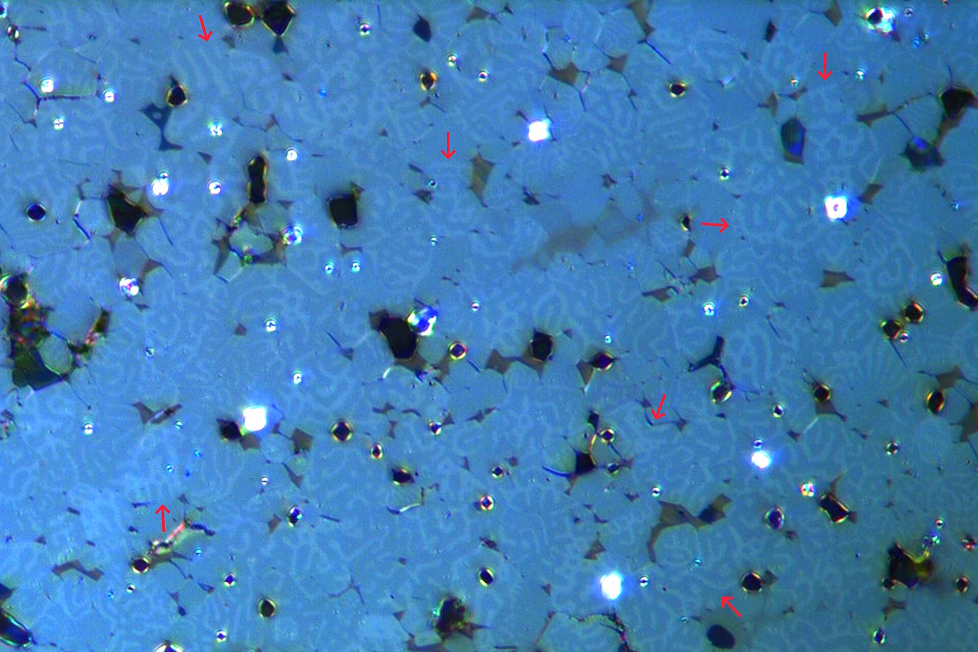
The magnetic domains in the grains of the steel samples show light and dark patterns in the images as a result of the longitudinal Kerr effect (refer to red arrows in figure 3). The rotation of the polarized light after interaction with the magnetic domains can lead to more intense (brighter) or less intense (darker) Kerr signals, or even extinction, after passing through the analyzer.
 due to the longitudinal Kerr effect.")
More Kerr-microscopy images of the same magnetized steel sample, going from an overview to seeing more detail, were recorded with an objective having a magnification of 20x, 50x, and 100x. Examples are shown in figure 4 below.

The results above show that the magnetic domains in the grains of steel alloys can be rapidly visualized with Kerr microscopy.
Summary and conclusions
Kerr microscopy utilizing the longitudinal Kerr effect offers an efficient way for visualizing magnetic domains in materials like steel alloys. Its application for R&D, quality control, and failure analysis can help the development of electrical and electronic devices, such as inductors, filters, and hard drives, which offer improved performance. Rapid imaging of magnetic domains at the surface of materials with Kerr microscopy offers advantages for the electrical and electronics industry.