Cryo Electron Tomography workflow and why a cryo light microscope is essential
Many scientific questions concerning the physiology and pathology of the human organism can only be answered by investigating the underlying cellular mechanisms. They are the foundation of any functional tissue, organ and the whole organism.
For understanding the function of different cell types under healthy and pathophysiological conditions, it is crucial to determine the participating biomolecules, such as proteins, and to examine their interaction at the molecular level.
To achieve this, Cryo Transmission Electron Microscopy (Cryo TEM) is used to resolve biomolecules within their cellular environment down to an unprecedented resolution below 1 nm. In this way individual proteins can be recognized without any labeling, “just” by their shape. Furthermore, even different conformations and their distribution within the cytoplasm can be distinguished.
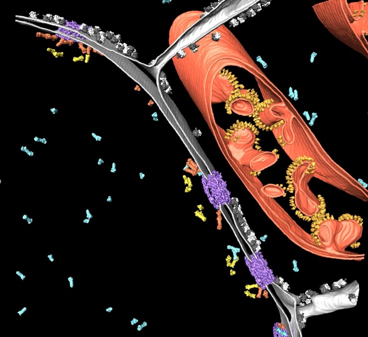
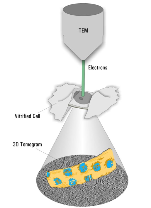
As a precondition, specimens have to be cryo-fixed by using sophisticated techniques (vitrification) avoiding destructive ice crystal formation. In contrast to other fixation techniques the proteins are maintained as close to the native state as possible. Afterwards, thin specimen (less than 300nm) can be directly assessed in the Cryo TEM. By tilting the sample, a 3-dimensional dataset of the observed sample volume can be created and reconstructed to obtain a 3D distribution of the relevant proteins of interest (Figure 2, Cryo Electron Tomography).
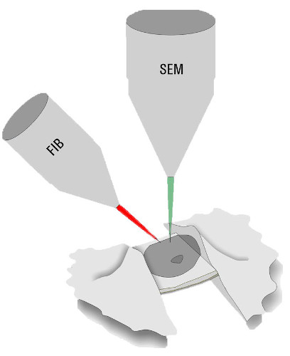
For observation of “thicker” parts of the specimens, the sample must be thinned. Beside cryo ultramicrotomy, Focused-Ion-Beam (FIB) Milling using a dedicated Cryo Scanning Electron Microscope is the method of choice. Two ion beam windows are positioned in a way that a thin ice sheet (lamella) of about 200 nm thickness is created at the area of interest. Like this, even parts of specimens, which could not be investigated are accessible for Cryo ET (Figure 3, FIB Milling).
As the workflow is tedious, many steps are needed while material and imaging time on the EMs is expensive, it is crucial to determine the quality of the sample and the presence of the target on the grid at an early stage. Furthermore, one major challenge is to find the precise milling positions to ensure that the lamella contains the protein(s) of interest.
To overcome these challenges, a cryo light microscope is an essential component of the workflow. Using a cryo light microscope the quality of the samples can be checked and, most importantly, the position of a structure of interest can be determined by using genetically encoded fluorescence tags (Figure 4).
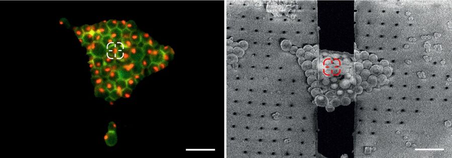
These markers can be visualized selectively and reveal the position of any structure of interest in 2D and 3D. Correlating the fluorescence and SEM images allows potential milling sites to be allocated (Correlative Light and Electron Microscopy, CLEM).
Although many challenges appear (safe cryo transfer of samples, potential water condensation on cold parts, objective used at low temperatures…) commercial cryo light microscopes are available.
Cryo light microscope and haze removal
Leica Microsystems provides a dedicated cryo light microscope, the THUNDER Imager EM Cryo CLEM, which is equipped with latest LED-technology and a highly sensitive, state-of-the-art scientific CMOS camera (Figure 5).
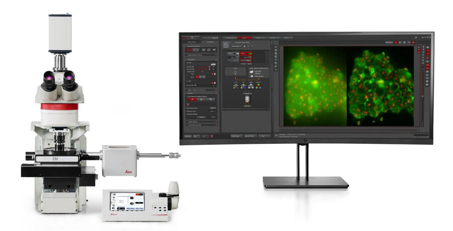
By following a software workflow, an overview of the complete sample holder (EM grid) can be created within less than a minute and the integrity of the support film on the grid can be checked. In a second step, the distribution of the target fluorescence signals and localization of suitable areas for subsequent FIB milling can be determined.
Unfortunately, although widefield microscopy is a very sensitive technique and, therefore, very well suited for cryo imaging, a background noise can be observed in the image. This background, mainly originating from out-of-focus regions of the sample, significantly reduces the contrast and potential signal-to-noise ratio (SNR) of the system. The recorded images typically show a haze and may not provide the level of detail needed to properly target the structures of interest.
To address this widefield issue, Leica Microsystems developed a brand new family of imaging systems, the THUNDER Imagers, which utilize Computational Clearing as the core technology. Each time an image is acquired, the out-of-focus background is detected and removed making the signal of interest directly accessible. At the same time, in the in-focus area, the edges and intensity of the specimen features remain.
Especially for biological samples, the background is usually not constant throughout the image. It can be quite variable over the field of view. Computational Clearing takes this automatically into account to make the in-focus signal immediately visible.
THUNDER Imagers offer three modes to choose from:
- Instant Computational Clearing (ICC)
- Small Volume Computational Clearing (SVCC)
- Large Volume Computational Clearing (LVCC)
ICC corresponds to computational clearing as described above.
SVCC and LVCC are combinations of computational clearing and decision-mask-based 3D deconvolution dedicated to either thin samples (SVCC) or thick samples (LVCC). The adaptive image information extraction of the deconvolution methods follows a concept which evolved from LIGHTNING, Leica Microsystems´ adaptive deconvolution method, originally developed for confocal microscopy.
LIGHTNING uses a decision mask as a base reference to calculate an appropriate set of parameters for each voxel of an image series. In combination with a widefield point spread function (PSF), the functionality of LIGHTNING can be transferred to widefield detection (more information can be found here.
Resolution improvement with THUNDER
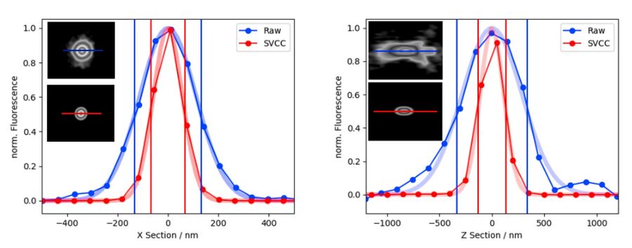
Applying Small Volume Computational Clearing (SVCC) to single, non-overlapping, diffraction-limited objects results in resolution enhancement. In the given example, a single bead of 40 nm diameter was imaged (100x magnifying lens, NA 1.44) and SVCC was applied. The sample-dependent result is a resolution enhancement* of approximately 2 times laterally (ratio FWHM in X using SVCC/Raw=0.51) and 2.5 times axially (ratio FWHM in Z using SVCC/Raw = 0.39).
*Resolution enhancement as defined by the apparent size of a point source emitting light. Separating two structures close to each other below the diffraction limit is not possible.
Vitrified samples imaged with the THUNDER Imager EM Cryo CLEM
As the THUNDER technology was first successfully used to image samples at ambient temperature, Leica experts later came up with the idea to apply this technique under cryo conditions. The haze-removal from widefield cryo images is particularly useful, as it not only improves the image quality, but ensures a more reliable identification of the structures of interest for the subsequent EM workflow steps (i.e., FIB Milling and TEM analysis).
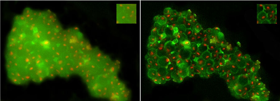
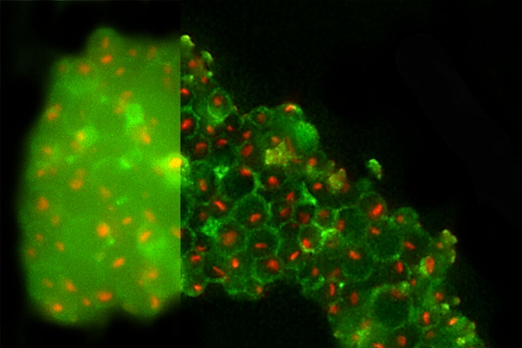
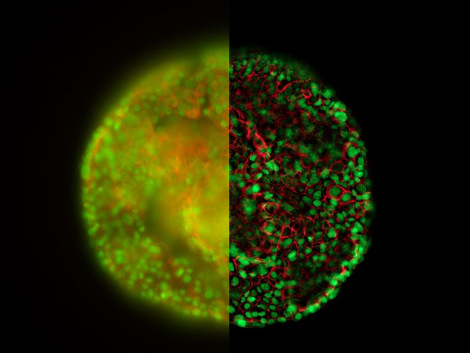
Figure 8 shows yeast cells observed with the THUNDER technique (THUNDER LVCC). On the left panel one can see that the out-of-focus haze of the green autofluorescence by the cell wall is disturbing the identification of nucleoli. One could argue, that the green fluorescence could be removed from the overlay image, but the visualization of the cell wall was needed simultaneously to identify nucleoli not being attached to it. After applying THUNDER, the background haze is reduced, while the signals are maintained; the cell walls and nucleoli are clearly visible and easier to identify for FIB Milling purposes.
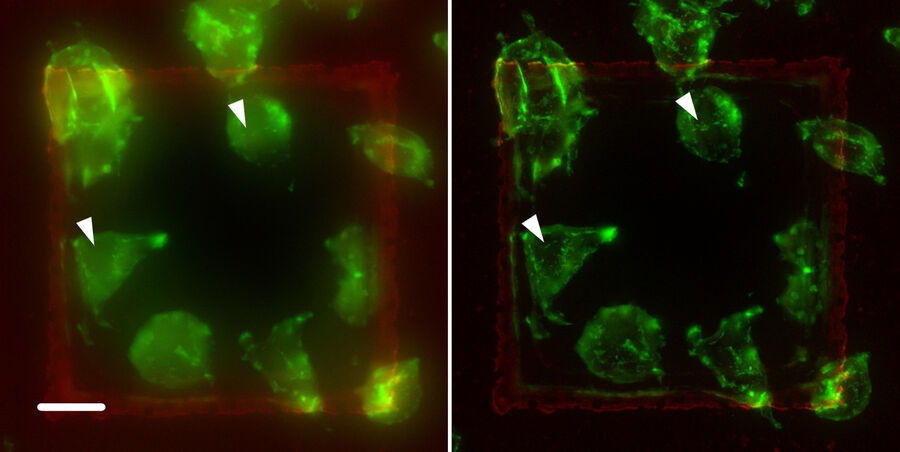
The application of the THUNDER technique was performed on different specimens. Figure 9 shows another example: A9 cells labeled with a green fluorescence dye bound to Phalloidin. Phalloidin selectively binds to fibrous actin, playing a structural role in eukaryotic cells. In the left panel, tiny structures are hidden by out-of-focus light (see arrows), but they become visible in the right panel after THUNDER SVCC.
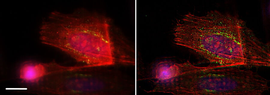
F-Actin is well-suited for THUNDER imaging as it´s thin and fibrous structure shows improvements instantaneously. Together with F-actin labeled by mCherry, Figure 10 displays a vesicular structure as well: TGN46, a protein of the Trans-Golgi Network (TGN), is indicated by GFP fluorescence. The TGN directs new proteins to different subcellular destinations. THUNDER also reveals these small vesicular structures while removing the blur caused by out-of-focus light.
Summary
In this article, we showed how the THUNDER imaging technology from Leica Microsystems, using Computational Clearing, improves the quality of images taken from vitrified samples under cryogenic conditions. Even tiny structures can be made visible by removing the haze or blur mainly caused by out-of-focus light. The THUNDER imaging technology not only improves the image quality, but also helps make it easier to identify structures for subsequent EM analysis steps.
Related Articles
-

Streamline your EM Sample Preparation Workflow for Biological Applications
Master EM sample preparation, including ultramicrotomy, for life sciences in this expert eBook!
Nov 17, 2023Read article -

New Imaging Tools for Cryo-Light Microscopy
New cryo-light microscopy techniques like LIGHTNING and TauSense fluorescence lifetime-based tools…
Aug 17, 2022Read article -

How to Target Fluorescent Structures in 3D for Cryo-FIB Milling
This article describes the major steps of the cryo-electron tomography workflow including…
Mar 22, 2022Read article