

Light sources for widefield and confocal microscopy
For a conventional laser scanning confocal microscope, around 5 different laser sources can be needed to cover the excitation wavelengths of commonly used fluorophores. For example, a commonly used laser is the argon-ion laser which can produce a range of excitation wavelengths which are selected by filters. The argon-ion laser covers the green wavelengths of the excitation spectrum and these are used to excite fluorophores like FITC (fluorescein isothiocyanate). The yellow to red wavelengths of the excitation spectrum are covered by a helium-neon laser in which the range extends from approximately 543 to 632 nm. This spectrum is used to excite fluorophores like Texas Red and rhodamine. However, now there are confocal microscopes using white light lasers with a wavelength range from 440 nm to 790 nm [5,6].
Before light-emitting diodes (LED) were introduced as fluorescence light sources for widefield microscopy, the main sources of excitation light were gas arc lamps and these are still widely used today. The 2 arc lamps which are commonly found in widefield microscopes are the mercury- (also referred to as a “mercury burner” or “mercury vapor lamp”) and the xenon-arc lamp. The mercury-arc lamp provides excitation wavelengths across much of the visible spectrum (refer to figure 2), however, this illumination is not uniform and the main peaks are within the near-ultraviolet (UV) wavelengths (313, 334, 365, 405, and 436 nm) with 2 other peaks in the green/yellow part of the spectrum at 546 and 579 nm.

Compared to mercury-arc lamps, xenon-arc lamps provide excitation wavelengths across most of the visible spectrum, but the peaks within this range do not reach the intensity of mercury ones. Although xenon-arc lamps do not extend as far into the UV part of the spectrum compared to mercury ones, their excitation range is shifted further into the infrared wavelengths.
Although these lamps are extremely intense light sources for fluorescence microscopy [7], they are not without inherent problems. The lifetime of these bulbs is limited with a mercury-arc lamp lasting typically 200 to 300 hours and a xenon-arc lamp lasting between 400 and 600 hours. Because they have restricted lifetimes, a careful note of the hours used should be kept with the microscope (although some systems have a built-in recorder of hours used). If gas-arc lamps are used beyond their recommended lifetime range, there is a danger that the tubes can explode. Furthermore, if the lamps are regularly switched on and off, it can significantly reduce the lifetime of the bulbs, so this needs to be taken into consideration. Used arc lamps need to be disposed of carefully and should be done so according to laboratory or institute regulations. Replacement and alignment of such lamps are covered in these 2 referenced articles [8,9].
Despite some of the drawbacks highlighted above, the mercury-arc lamp is still considered to be a fundamental light source for widefield fluorescence microscopy due to the intensity of light produced.
The new generation of LED light sources for microscopy provide not only a full spectrum of excitation wavelengths (from around 365 to 770 nm), but also an intensity comparable to arc lamps. A major advantage of them over the arc lamps is the LED lifetime which can be up to 50,000 hours with no warm-up or cool-down periods required. This also saves time as an LED unit needs only to be aligned when initially installed. Finally, waste heat is a problem with arc lamps and, as a consequence, they are housed in special units next to the microscope. As most of the electrical input with an LED is converted to light, they produce little waste heat. An example of a Leica LED light source for fluorescence microscopy is shown below (refer to figure 3).

Image capture for widefield and confocal microscopy
As highlighted above, the confocal scan head contains an array of photomultiplier tubes (PMTs) [4] for the collection of photons from the sample. Typically, a confocal scan head will contain at least three PMTs which are responsible for collecting red, green and blue light, but additional PMTs are commonly used for the collection of transmitted or reflected light. The PMTs are not the same as digital cameras, but are comprised of vacuum tubes which have a photon entry window at one end and an electron multiplying component in the body of the tube (refer to figure 4). The amount of photons collected is converted to an electrical signal before the image is finally assembled and displayed. Many confocal systems are also equipped with cameras similar to those used for widefield microscopy.
Image capture in widefield microscopy is facilitated by a digital microscope camera (refer to figure 4) [10]. These digital cameras contain semiconductor-based detectors and the most common sensors are charge coupled devices (CCDs), complementary metal oxide semiconductors (CMOSs), and sCMOS (scientific CMOS) [10]. There are many similarities between CCD and CMOS cameras, although they process the image signal in different ways, consequently, which can affect the capture time of the camera as well as other factors, such as the signal-to-noise ratio. The framerate of a CCD-based camera can be 10-times slower than a CMOS sensor due to differences in the intrinsic nature of how they function. Therefore, the choice of camera is dependent on the dynamic nature of the specimen being observed.

Configurations of a widefield microscope
Widefield microscopes are either upright, where the specimen is illuminated from below, or inverted, where the specimen is illuminated from above (refer to figure 5). This configuration has an influence on the type of specimen which can be investigated. Upright microscopes are commonly used for applications with fixed samples mounted on glass slides. Inverted microscopes have been invented to watch living cells which are commonly grown in liquid solutions. Only a configuration with the objective below and the condenser above the sample stage guarantees the objective to be in a close enough proximity to the specimen.
 an upright microscope features the objective above and the condenser below the specimen. Right) on an inverted microscope, this setup is reversed.")
Incident-light fluorescence or epi-fluorescence microscopy describes microscopy where the same objective lens is used to both illuminate and collect the emitted light from a sample or specimen [11]. Light travels from the light source, passes through a filter set, then a dichromatic mirror, and the shorter wavelength excitation light is reflected onto the specimen via an objective. The longer wavelength emitted light from the specimen travels back through the objective and then passes through the dichromatic mirror to be observed via the eyepieces and/or a digital camera.
Trans-illumination microscopy techniques include contrast methods, such as phase contrast and differential interference contrast (DIC). However, trans-fluorescence microscopy is a method which is neither well known nor well used. This method negates the use of dichromatic lenses and, instead, the excitation light passes through the condenser and specimen and the emission light is collected by the objective. However, the technique had many initial problems, such as high levels of background and difficulties in optically matching the condenser and objectives [12]. Recent advances which overcome these problems have led trans-fluorescence imaging to be used in areas like in-vivo imaging and dental research [13].
Contrast methods used for widefield microscopy
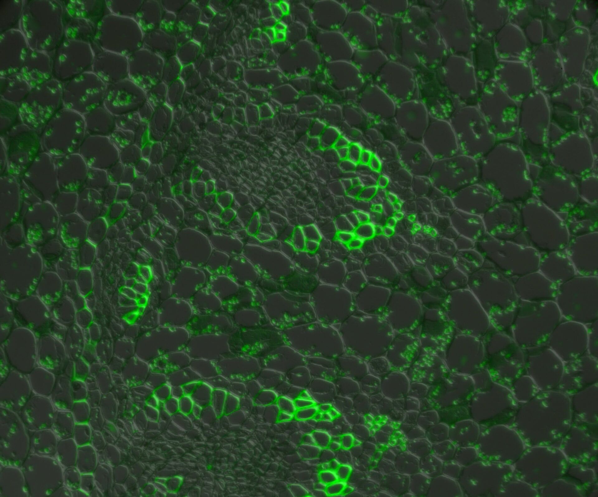
Contrast methods of microscopy [14] including differential interference contrast (DIC) [15] and phase contrast [16] microscopy can be used in conjunction with widefield fluorescence microscopy [17] (refer to figure 6).
Combining widefield fluorescence microscopy and contrast techniques can provide valuable information obtained from images of viability and morphology. A confocal system has the ability to simultaneously capture images with both contrast and fluorescence illumination which can be overlaid using image analysis software. However, for widefield fluorescence microscopy, such simultaneous imaging requires the use of a split-view camera adaptor or 2 separate cameras, one for contrast and the either for fluorescence. More often serial imaging is done, i.e., a fluorescence image will be captured by the camera followed by a change in optics to contrast illumination and then the same camera will capture the contrast image. These images can then be combined using image analysis software.
 neuronal cell culture in DIC; Middle) phase contrast; and Right) fluorescence microscopy.")
Resolution achieved with widefield microscopy
The resolution of a microscope is simply the ability to distinguish detail in a specimen. It is the minimum distance between 2 distinct points of a specimen where they can still be viewed as separate entities [18].
For all conventional modes of operation, the resolution of optical microscope systems, including confocal, is determined by the numerical aperture (NA) and the wavelength of light. The limit of resolution is around 200 nm. In a perfectly aligned optical microscope system with the highest NA optics, the limit of resolution is roughly half of the wavelength of light used to image the specimen (or excite the fluorophores). When comparing widefield to conventional confocal microscopy, the theoretical limits of resolution are similar for both methods.
However, the actual resolution achieved by a widefield microscope is exacerbated by background fluorescence. As highlighted above, the entire specimen is illuminated at the same time and therefore regions above and below the focal plane will also fluoresce and be seen by the viewer through the eyepieces or captured by a camera. As a result, emission wavelengths from a fluorophore can be somewhat masked by this background fluorescence leading to an overall decrease in the signal-to-noise ratio and a subsequent decrease in achievable resolution and contrast.
In a confocal system, the pinhole (within the scan head) [19] is used to block any out-of-focus light from reaching the detectors. Although this has the advantage of producing a sharply focussed image by blocking background and autofluorescence, some of the photons may have originated from the focal plane. This means that some of the meaningful information could potentially be lost due to the pinhole. There is a balance between the sharp images produced on a confocal system and inadvertently collecting out-of-focus light with a widefield microscope. However, using a post-acquisition process like computational clearing or deconvolution [20] can resolve the blurring and haze problem (refer to figure 7). Such computational processes can reassign photons to their point of origin.


Figure 7: Widefield fluorescence microscope image of a paramecium before and after computational clearing.
Advanced techniques: FRAP and super-resolution
Fluorescence recovery after photobleaching (FRAP) [21] is used to examine the mobility of molecules over a period of time. This technique was initially used to study the dynamics and fluidity of lipid molecules in cellular membranes, but it can also be used to study proteins within organelles or the cytoplasm. In a FRAP experiment, a fluorescent probe is covalently attached to a molecule of interest or the target protein is engineered to express a fluorophore, such as green fluorescent protein (GFP) [22-24].
Once the fluorophore of interest has been localised, a target region within the cell is deliberately (and irreversibly) photobleached [25] to erase all of the fluorescence. Over time, the bleached area will gradually become fluorescent again as more tagged target proteins move into the region whether passively (by diffusion) or actively (by transport). Such experiments can yield useful results in determining real-time movements and properties of proteins with the cellular environment (refer to figure 8).

Although FRAP experiments were previously carried out using a confocal microscope, it can also be done with widefield solutions nowadays. Compared to conventional confocal-based FRAP experiments, widefield FRAP can offer higher imaging speeds with state-of-the-art cameras and also protect cells and specimen regions of interest from excessive photo-stress, as can be caused by confocal systems.
Super-resolution microscopy can image beyond the resolution limit of 200 nm for conventional widefield microscopes. Several super-resolution techniques have been developed over time:
- Single molecule localization techniques where small proportions of a fluorophore signal are collected over time to build up a final image. As the name suggests, it is possible to capture and image single molecules if the experimental conditions allow.
- Structured illumination microscopy (SIM) is a widefield technique where patterns are generated in the phase and amplitude of the illuminating light. As the sample is imaged, similar patterns are created and the interference between the generated and specimen-based patterns is used to determine the intracellular structure.
- Stimulated emission depletion (STED) microscopy, a confocal technique, requires 2 lasers where one is for excitation of fluorophores and the other is a circular shaped laser beam [26,27]. The circular beam “depletes” the emission from the same fluorophores resulting in a smaller region of image capture.
One of the single molecule localization techniques which is achievable with widefield microscopy is known as direct stochastic optical reconstruction microscopy (dSTORM) or also ground state depletion followed by individual molecule return (GSDIM) microscopy.
GSDIM or dSTORM utilises lasers and photo-switchable fluorescent probes which are switched off and on to build up an image over time. The majority of the fluorescent probes are induced into a ”dark-state” energy level where they cannot emit photons. As a result, only single and well separated fluorophores can be located with nanometer precision.
References
- Confocal microscope articles, Science Lab, Leica Microsystems.
- C. Greb, Fluorsecent Dyes: An Overview, Science Lab (2022) Leica Microsystems.
- C. Greb, Fluorescent Proteins – Introduction and Photo Spectral Characteristics, Science Lab (2012) Leica Microsystems.
- R.T. Borlinghaus, H. Birk, Which Sensor is the Best for Confocal Imaging? The Hybrid Photodetectors (HyD) are! Why that is the case is explained in this short article, Science Lab (2018) Leica Microsystems.
- STELLARIS White light lasers: Expanded multicolor capability. Fewer compromises, Science Lab (2020) Leica Microsystems.
- R.T. Borlinghaus, L. Kuschel, White Light Laser: The Ultimate Source for Confocal Microscopy, Science Lab (2012) Leica Microsystems.
- W. Ockenga, An Introduction to Fluorescence, Science Lab (2011) Leica Microsystems.
- B. Braun, W. Wittke, Video Tutorial: How to Change the Bulb of a Fluorescence Lamp Housing, Science Lab (2012) Leica Microsystems.
- B. Braun, W. Wittke, Video Tutorial: How to Align the Bulb of a Fluorescence Lamp Housing, Science Lab (2012) Leica Microsystems.
- C. Müller, C. Greb, K. Schwab, Definitions of Basic Technical Terms for Digital Microscope Cameras and Image Analysis, Science Lab (2016) Leica Microsystems.
- C. Greb, Milestones in Incident Light Fluorescence Microscopy: Fluorescence Microscopy Pioneers - Johan Sebastiaan Ploem, Science Lab (2017) Leica Microsystems.
- P.T. Tran, F. Chang, Transmitted Light Fluorescence Microscopy Revisited, Biological Bulletin (2001) vol. 201, num. 2, pp. 235-236, DOI: 10.2307/1543340.
- V. Ntziachristos, Fluorescence Molecular Imaging, Annual Review Biomedical Engineering (2006) vol. 8, pp. 1–33, DOI: 10.1146/annurev.bioeng.8.061505.095831.
- W. Ockenga, Optical Contrast Methods: Physical Background and Fields of Application, Science Lab (2011) Leica Microsystems.
- W. Ockenga, Differential Interference Contrast (DIC), Science Lab (2011) Leica Microsystems.
- W. Ockenga, Phase Contrast: Making Unstained Phase Objects Visible, Science Lab (2011) Leica Microsystems.
- W. Ockenga, Fluorescence in Microscopy, Science Lab (2011) Leica Microsystems.
- M. Wilson, J. DeRose., C. Greb, Microscope Resolution: Concepts, Factors and Calculation: Airy discs, Abbe’s diffraction limit, the Rayleigh Criterion, and the point spread function (PSF), Science Lab (2023) Leica Microsystems.
- R.T. Borlinghaus, Pinhole Effect in Confocal Microscopes, Science Lab (2017) Leica Microsystems.
- C. Greb, J. DeRose, R.T. Borlinghaus, Going beyond deconvolution: Acquiring sharper 3D images of thick biological specimens with widefield microscopy, Science Lab (2020) Leica Microsystems.
- J. Schröder, Fluorescence Recovery after Photobleaching (FRAP) and its Offspring, Science Lab (2011) Leica Microsystems.
- C. Greb, Fluorescent Proteins - From the Beginnings to the Nobel Prize, Science Lab (2012) Leica Microsystems.
- C. Greb, Fluorescent Proteins - Introduction and Photo Spectral Characteristics, Science Lab (2012) Leica Microsystems.
- C. Greb, Fluorescent Dyes: An Overview, Science Lab (2022) Leica Microsystems.
- C. Greb, Basic Principles of Luminescence, Science Lab (2012) Leica Microsystems.
- Nanoscopy meets Lifetime: Introducing TauSTED: Learn more about TauSTED, what it is, how it works and what are the benefits for our research, Science Lab (2020) Leica Microsystems.
- S.W. Hell, J. Wichmann, Breaking the diffraction resolution limit by stimulated emission: stimulated-emission-depletion fluorescence microscopy, Optics Letters (1994) vol. 19, iss. 11, pp. 780-782, DOI: 10.1364/OL.19.000780
, Tropomyosin (cardiomyocytes, red) and GFP (primordial cardiac layer, green).")
 and astrocytes (green) in a cortical spheroid derived from human induced pluripotent stem cells.")